Caen ELS BEST User Manual Download Page 14

Introduction


BEST

 User’s Manual 

14 

1.3


PreDAC

 Overview 

The 

PreDAC

  is  a  (up to)  4-channel,  21-bit resolution,  wide-bandwidth  Digital to 

Analog Converter (DAC) which is especially designed for seamless operation within 
the 

BEST

 system. At the core of the 

PreDAC

 system there is a high-speed 16-bit 

digital to analog converter that uses dithering technique and active low-pass filtering 
to obtain a stable high accuracy (21-bit) output signal. 

This  device  is  capable  of  outputing  up  to  ±12  V  bipolar  voltage  with  an  ultimate 
resolution of 12 

V – i.e. 21 bits on the bipolar full output range. Output voltage noise 

is suppressed using a 4

th

 order active low-pass filter with cut-off frequency (-3 dB) of 

10 kHz. Its minimized temperature-induced drifts, good linearity and very low noise 
levels enable users to perform high-precision voltage signal generation. 

The  standard 

PreDAC

  has  two  voltage  output  channels  but  can  be  optionally 

upgraded to have three or even four output channels on a single unit. It is housed in a 
light,  robust  and  extremely  compact  metallic  box  that  can  be  placed  as  close  as 
possible  to  the  actuator  power  driver/amplifier  in  order  to  reduce  cable  lengths  and 
consequently minimize possible noise pick-up on the analog signal path. It is specially 
suited  for  applications  where  multi-channel  simultaneous  actuations  are  required,  a 
typical  application  being  control  of  position  (X,  Y)  and  intensity  (I

0

)  of  the  photon 

beam in synchrotron radiation or XFEL X-ray beamlines.  

The 

PreDAC

  communication  to  a  host  PC  when  used  as  a  standalone  unit  is 

guaranteed  by  a  standard  10/100/1000  Mbps  Ethernet  TCP/IP  protocol  while  its 
integration  in  the 

BEST

  (Beamline  Enhanced  Stabilization  Technology)  system  is 

performed via the SFP link available on the rear panel. 
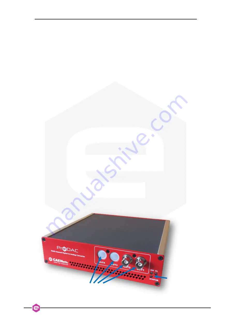
The 

PreDAC

  unit  and  its  I/O  connections  can  be  easily  seen  in 

Figure  6

    (front) 

and in 

Figure 7


(rear). 


Output Channels


ON,  CL  and 
STATUS LEDs


Summary of Contents for BEST

Page 1: ...1 BEST Beamline Enhanced Stabilization Technology User s Manual All Rights Reserved CAEN ELS s r l Rev 1 6 March 2022 BEAMLINE ELECTRONIC INSTRUMENTATION...

Page 2: ...This product is certified CAEN ELS s r l Via Vetraia 11 55049 Viareggio LU Italy Mail info caenels com Web www caenels com...

Page 3: ...Unit COMP BEI0004 which includes 3 Optical Cables OM2 50 125 m Multimode Duplex DK 2533 10 length 10 m 6 SFP Fiber Optic Transceivers 4 25Gbps 850nm 3 V 3 6 V LC Duplex Pluggable FTLF8524P2BNV The BE...

Page 4: ...3 1 CONTROLLER SCHEMATIC 22 4 BEST LOCAL GUI 24 4 1 MAIN WINDOW 24 4 1 1 Graph XY 25 4 1 2 Feedback Control Panel 26 4 1 3 PID Configuration Panel 29 4 2 LOGIN 34 4 3 BEAMLINE CONFIGURATION 35 4 3 1 B...

Page 5: ...s added 1 0 1 August 18th 2014 Password font corrected 1 1 October 29th 2014 Manual graphics changed 1 2 September 25th 2018 Manual Updated 1 3 October 10th 2019 Added EPICS documentation 1 4 June 3rd...

Page 6: ...part of the instrument WARNING Do NOT open the boxes CAEN ELS s r l declines all responsibility for damages or injuries caused by an improper use of the Modules due to negligence on behalf of the Use...

Page 7: ...d Before you use the device inspect the instrument for possible cracks or breaks before each use Do not operate the device around explosives gas vapor or dust Always use the device with the cables pro...

Page 8: ...vironmental requirements for a correct operation of the instrument Environmental Conditions Requirements Operating Temperature 0 C to 45 C Operating Humidity 30 to 85 RH non condensing Storage Tempera...

Page 9: ...ock i e BEST Central Unit the actuator block i e PreDAC device A simplified block diagram of the BEST architecture is shown in the following figure Figure 1 Simplified architecture of the BEST instrum...

Page 10: ...ents In this way it is possible to close the control loop and to stabilize the X ray beam The FPGA based hardware architecture allows performing the control algorithms at a maximized speed and with ve...

Page 11: ...ompact metallic box that can be placed as close as possible to the current source BPM detector in order to reduce cable lengths and minimize possible noise pick up on the weak signals coming from the...

Page 12: ...such as stabilization intensity monitoring and positioning of the photon beam The FPGA logic receives the acquired X ray data from all TetrAMM devices via a high speed SFP link The received data i e c...

Page 13: ...physical quantities data i e raw TetrAMM currents beam position and intensity FFT CSP control the beam position with a simple point and click positioning feature or by entering a setpoint manually Re...

Page 14: ...tandard PreDAC has two voltage output channels but can be optionally upgraded to have three or even four output channels on a single unit It is housed in a light robust and extremely compact metallic...

Page 15: ...uts in order to prevent any possible damage to the connected units for example the piezoelectric actuators To perform this task please refer to the MIN and MAX Commands of the PreDAC User s manual Pow...

Page 16: ...sential to determinate position and the intensity of the X ray beam The TetrAMM must be connected with the phBPM using the four analog input connectors placed on the front side of the unit The BNC con...

Page 17: ...SHV output connector The SHV connector is similar to the BNC but uses a very thick and protruding insulator Figure 9 The insulation geometry makes the SHV connector safe for handling high voltage sou...

Page 18: ...mplifier in order to reduce cable lengths i e cable capacitance and to minimize consequent noise pick up It is also highly recommended to use high quality BNC cables to connect the PreDAC outputs 2 3...

Page 19: ...the PreDAC and TetrAMM units there is a dedicated SFP slot providing the communication between the devices and the BEST Central Unit Firstly it is necessary to insert the SFP optics transceiver module...

Page 20: ...Central Unit Similar as for the TetrAMM and PreDAC devices the SFP optic transceivers should be plugged into the dedicated slots on the rear side of the BEST Central Unit but in this case the correct...

Page 21: ...s or with a 230 V 50 Hz AC Line e g Europe be sure to select the correct input voltage rating by switching the AC Line Voltage Select switch placed on one side of the box Possible switch positions one...

Page 22: ...to select which BPM should be assigned to which PID controller An averaging module is placed in between the BPM selector and the PID This module configurable by the user defines the update frequency s...

Page 23: ...BEST User s Manual BEST Central Unit Overview 23 Figure 15 BEST controller functional overview...

Page 24: ...he currents first read by the TetrAMMs and then transformed in positions using the usual difference over the sum equations and the BPM scaling parameters see 4 3 for more info Various possible plots c...

Page 25: ...edback system What these setting are and where to find them will be clarified in the following sections 4 1 1 Graph XY The Graph XY window in the upper section of the GUI shows the X ray beam position...

Page 26: ...setpoint The red rectangle always larger than the green one shows the Region Of Convergence ROC i e the area where the PID controller acts on the beam position If in any case the beam position leaves...

Page 27: ...re 21 which groups all the main feedback control input output parameters The statistics section tab reports mean values and standard deviations of X Y and intensity I0 of the BPM data at the maximum s...

Page 28: ...tomatically stopped Before starting again the feedback with the Enable feedback button it s necessary to set back the PID status and its output to the initial values this can be done with the Reset Co...

Page 29: ...he FPGA logic for the BEST fast feedback computation algorithms The BEST system can control and stabilize up to three variables 1 X horizontal position 2 Y vertical position 3 I0 intensity A digital f...

Page 30: ...eraging is performed on 1000 samples and Real freq will exactly be 100 Hz while if the user selects 90 Hz the average is performed on the closest possible integer number of samples 1112 and Real freq...

Page 31: ...ier or even to the actuator itself For example piezoelectric actuators often have asymmetric input voltage ranges much wider in a given polarity than in the opposite N B we point out that it is possib...

Page 32: ...rst BPM usually in yellow with except for the Currents Graph Tab where and additional graph tab is created for the second BPM 4 1 4 1 FFT Graph Tab The FFT Graph Tab shows the real time FFT of the mai...

Page 33: ...BEST User s Manual BEST Local GUI 33 4 1 4 3 DAC Graph Tab 4 1 4 4 Position Graph Tab 4 1 4 5 Intensity Graph Tab...

Page 34: ...s WeAreTheBest User mode does not allow changing the beamline related settings but provides authorization to change setpoints and feedback parameters and configuration Username for this mode is user a...

Page 35: ...hBPM system on the right A quick overview of the available beamline configuration options are represented in the following sections 4 3 1 Beam Position Monitor The BPM Beam Position Monitor section al...

Page 36: ...eamline either intrinsically with a different geometry e g diamond based phBPM or with the phBPM system rotated CW by 45 in order not to get shadowed by the first unit upstream Then the computation ne...

Page 37: ...e 27 Figure 27 ROC ROI Settings window The Region of Convergence ROC is the maximum area where the PID controller stabilizes the beam to a certain setpoint If for any reason the beam position goes out...

Page 38: ...intensity goes back to values above the set threshold Please note the difference between the stop condition if the ROC input fields are checked that fully freezes the feedback loop when the beam posit...

Page 39: ...onfiguration the user can change the TetrAMM reading range gain Available options are 0 higher current range and 1 lower current range 4 3 SFP Info The SFP Info window which is accessible from Setting...

Page 40: ...amplitude generated by the PreDAC is swept through a pre defined frequency range and in parallel the system response is read by the TetrAMM and analyzed by the Central Unit The Frequency Analysis Too...

Page 41: ...BEST User s Manual BEST Local GUI 41 Figure 31 Frequency analysis tool window...

Page 42: ...github platform It is based on the functionalities offered by the BEST library that is part of the BEST software suite and constantly updated with new features An API reference manual of the BEST lib...

Page 43: ...43 5 1 EPICS IOC Integration Start the BEST Local User Interface Figure 32 Run the BEST Local User Interface In order to start the EPICS server double click the BEST EPICS IOC application framed in b...

Page 44: ...ICS server will return the EPICS server shell Figure 33 Run the BEST EPICS server The system shows that the procedure is completed therefore EPICS control is allowed Figure 34 BEST EPICS server initia...

Page 45: ...side assuming EPICS is correctly installed the user has access to all the commands available e g caput caget camonitor etc 5 2 BEST login using EPICS As for the BEST Local User Interface also EPICS re...

Page 46: ...e that the feedback controller is disabled The PreDAC output MUX has to be set to 0 This means that the PreDAC is controlled by software i e from the Linux driver through PCIe Lastly the user can set...

Page 47: ...implemented in FPGA logic performs all the calculations in order to get the X Y positions or intensity to the user defined setpoint The user must firstly ensure that the PreDAC output is driven by har...

Reviews: