background image

IDRO PRINCE

3

 12-16-23-23 H

2

O - IDRO PRINCE 30-30 H

2

O - AQUOS

3

 16-23-23 H

2

O - IDRON 16-22 AIRTIGHT - MIRA 16-22 - TESIS 16-23 AIRTIGHT -  HIDROFIRE 22.8

57

12.11  FAILED START-UP

If during ignition no flame develops, the boiler will go into alarm condition.

12.12  ANTIFREEZE FUNCTION

If the probe in the boiler detects a water temperature of less than 5°C, the circulation pump is automatically activated to prevent 

the system from freezing.

12.13  PUMP ANTI-SEIZURE FUNCTION

If the pump is not used for prolonged periods, it is activated periodically for a few seconds to prevent it from seizing up.

TAMPERING WITH THE SAFETY DEVICES IS PROHIBITED

If the product is NOT used as described in this instruction manual, the manufacturer declines all liability for 

any damage caused to persons and property. The manufacturer furthermore refuses to accept responsibility 

for damage to persons and property arising from the failure to observe all the rules contained in the manual 

and in particular:

• All the necessary measures and/or precautions must be adopted when performing maintenance, cleaning 

and repairs.

• Do not tamper with the safety devices.

• Do not remove the safety devices.

• Connect the product to an efficient smoke expulsion system.

• Verify that the room in which the appliance will be installed is adequately ventilated.

The product can be started-up and the automatic function of the probe restored only after having eliminated 

the cause that triggered the safety system. This manual will help you understand which anomaly has occur-

red, and explain how to intervene according to the alarm message displayed on the appliance.

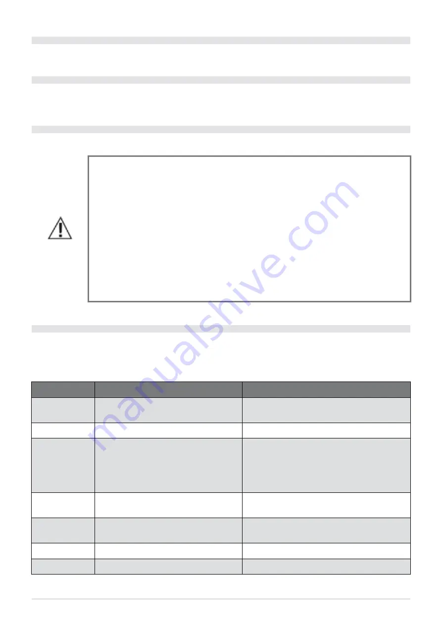
12.14  ALARM ALERTS

Whenever an operating condition other than that designed for the regular operation of the boiler occurs, there is an alarm condi-

tion.

The control panel gives information on the reason of the alarm in progress. A sound signal is not envisioned for alarms A01-A02 

only so to PANEL ALERTnot disturb the user in the event of pellets running out in the hopper during the night.

PANEL ALERT

TYPE OF PROBLEM

SOLUTION

A01

The fire does not ignite.

Check whether the brazier is clean / level of pellets in 

the hopper.

A02

The fire goes off abnormally.

Check the level of pellets in the hopper.

A03 Thermostat 

alarms

The temperature of the pellets hopper or the 

water temperature exceed the envisioned 

safety threshold. 

Wait for the cooling stage to end, cancel the alarm and 

restart the boiler setting the fuel loading at minimum 

(SETTINGS menu - Pellets recipe). If the alarm persists, 

contact the service centre. Check if the room fan works 

properly (if present).

A04

Smoke overheating.

The set smoke threshold has been exceeded. Reduce 

pellets loading (SETTINGS menu - Pellets recipe).

A05 Pressure 

switches alarm

Smoke pressure switch intervention or water 

pressure insufficient.

Verify chimney obstruction / door opening or hydraulic 

system pressure.

A08

Abnormal smoke fan operation.

If the alarm persists, contact the service centre.

A09

Smoke probe faulty.

If the alarm persists, contact the service centre.

Summary of Contents for HIDROFIRE 22.8

Page 1: ...A 16 TESIS 16 AIRTIGHT IDRO PRINCE3 23 AQUOS3 23 IDRON 22 AIRTIGHT HIDROFIRE 22 8 MIRA 22 TESIS 22 AIRTIGHT IDRO PRINCE3 23 H2 O AQUOS3 23 H2 O IDRO PRINCE 30 IDRO PRINCE 30 H2 O C A MERA STAGNA C H A M B R E É T A N C H E S E A L E D C H A M B E R E S TANCA HERMETISCH G E S L O T E N K A M E R C Â M A R A E S T A N Q U E Σ Φ Ρ Α Γ Ι Σ Μ Έ Ν Ο Σ Θ Ά Λ Α Μ Ο Σ T E STED 50 PA EN 16 5 1 0 ...

Page 2: ...LLETS 30 6 2 SAFETY 31 6 3 USERTRAINING 31 7 PLUMBING CONNECTION 32 7 1 PLUMBING SYSTEM CONNECTION 32 7 2 CONNECTION DIAGRAM IDRO PRINCE3 12 32 7 3 CONNECTIONDIAGRAM IDROPRINCE3 16 23 AQUOS3 16 23 IDRON 16 22 AIRTIGHT HIDROFIRE 22 8 MIRA 16 22 TESIS 16 23 AIRTIGHT 33 7 4 CONNECTION DIAGRAM IDRO PRINCE 30 34 7 5 CONNECTION DIAGRAM IDRO PRINCE3 23 H2 O AQUOS3 23 H2 O 35 7 6 CONNECTION DIAGRAM IDRO P...

Page 3: ...TDOWN ON THE PANEL OFF WITH FLASHING FLAME 56 12 17 BLACKOUTWITHTHE BOILER ON 56 12 18 BLACKOUT ABOVE 10 WITH BOILER IN SHUTDOWN STAGE 57 13 RECOMMENDATIONS FOR SAFE USE 57 14 CLEANING AND MAINTENANCE 58 14 1 DAILY OR WEEKLY CLEANING USER S RESPONSIBILITY 58 14 2 CLEANINGTHE GLASS 59 14 3 CLEANINGTHE EXCHANGER ANDTHE COMPARTMENT UNDERTHE BRAZIER EVERY 2 3 DAYS 59 14 4 PIPE UNIT CLEANING 59 14 5 SM...

Page 4: ...s less than 35KW refer to Ministerial Decree 37 08 and all qualified instal lation technicians with the requisites must issue a certificate of compliance for the installed system System is intended as Stove Chimney Air vent 1 1 REVISIONS TO THE PUBLICATION The content of this manual is strictly technical and property of CADEL srl Nopartofthismanualcanbetranslatedintoanotherlanguageand oralteredand...

Page 5: ...e forexample heatresistantglovesor cooltouch typeactivationsystems Using the product with the door open or the glass broken is prohibited The product must be electrically connected to a mains equipped with an efficient earthing system Switch the product off in the event of a breakdown or poor operation The unburnt pellets that accumulate in the burner after every failed ignition must be removed be...

Page 6: ...normalwearlistedbelow foradura tion of 2 two years from the date of purchase which is demonstrated by a supporting document invoice and or receipt showing the name of the retailer and the date of sale the forwarded warranty certificate filled out within 8 days of the purchase Furthermore inordertomakethewarrantyvalidandoperative theappliancemusthavebeeninstalledandcommissionedsolely by qualified p...

Page 7: ...ssary to resolve their improper technical manoeuvres tampering or in any case damaging factors for the appliance that cannot be attributed to original defects Without prejudice to the limits imposed by laws or regulations atmospheric pollution and noise containment are not covered by the warranty The company declines all liability for any direct or indirect damage to people animals or property as ...

Page 8: ...rce In any case follow For the heating system Local requirements for connection to the chimney Local requirements for fire prevention standards For the electrical parts EN 60335 Household and similar electrical appliances Safety Part 1 General requirements Part 2 Particular requirements for appliances with gas diesel and solid fuel burners equipped with electrical connections 3 2 PELLETS Wood pell...

Page 9: ...rticular he she must make sure that there is an appropriate combustion air vent and smoke exhaust compliant with the type of product installed other stoves or installed appliances do not create a vacuum in the room where the product is installed 15 Pa of vacuum maxi mum is allowed only for airtight appliances smoke does not flow back into the room when the product is on smoke is extracted in compl...

Page 10: ...ossession Check with the local authorities whether there are stricter standards regarding the combustion air vent the smoke exhaust system the flue the chimney cap The company declines all liability regarding poor stove operation if it can be attributed to using an incorrectly sized flue that does not meet the standards in force 3 6 FLUE The flue or chimney is extremely important for forced draft ...

Page 11: ...twin wall chim neys in A 316 or refractory material It must be externally insulated to prevent condensation and to reduce the smoke cooling effect It must not be near combustible or highly flammable materials with an air or insulating material gap check the chimney distance indicated by the manufacturer according to EN 1443 The chimney opening must be in the same room in which the ap pliance is in...

Page 12: ...HIDROFIRE 22 8 12 A B C D 15 E F Fig 5 15 roof LEGEND Fig 5 A min 1 00metre B distance 1 85metres C distance 1 85metres D 0 50metresbeyondthetop E 0 50metres F backflowarea A B C D E 30 F Fig 6 30 roof LEGEND Fig 6 A min 1 30metres B distance 1 50metres C distance 1 50metres D 0 50metresbeyondthetop E 0 80metres F backflowarea ...

Page 13: ...HIDROFIRE 22 8 13 A B D 60 E C F Fig 7 60 roof LEGEND Fig 7 A min 2 60metres B distance 1 20metres C distance 1 20metres D 0 50metresbeyondthetop E 2 10metres F backflowarea A B C D E 45 F Fig 8 45 roof LEGEND Fig 8 A min 2 00metres B distance 1 30metres C distance 1 30metres D 0 50metresbeyondthetop E 1 50metres F backflowarea ...

Page 14: ...itional clay square section chimney with hollow insula ting inserts Avoid chimneys with rectan gular inner section in which the ratio between the longer side and the shorter side is greater than 1 5 for example 20x40 or 15x30 3 9 MAINTENANCE Fluesmustalwaysbeclean asbuild upsofsootorunburntoilreducethecross section blockingdraft compromisingproperstove operation and inlargeamounts cancatchfire Hav...

Page 15: ...m in which the pro duct is installed see Solution 2 Fig 12 Adjacent rooms do not include bedrooms bathrooms garages and rooms at risk for fire in general During installation you must check the minimum distances necessary to be able to draw air from the outside Consider doors and windows that could interfere with proper air flow to the stove see the diagram below Theairventmusthavean80cm2 minimumto...

Page 16: ...s long every pipe elbow is to be considered equivalent to a linear metre For the pipe coupling see the back of the stove For stoves installed in studio flats bedrooms and bathrooms where permitted the combustion air must be connected to the out side Inparticular forairtightstoves saidconnectionmustbeairtightsoasnottojeopardisetheoverallairtightfeatureofthesystem MIN 1 5 m MIN 1 5 m MIN 1 5 m MIN 0...

Page 17: ... not directly vent com bustion products either towards closed spaces or to the outdoors Specifically it is recommended to check the safety distances on the flue plate data that must be complied with in the presence of combustiblematerialsandthetypeofinsulatingmaterialtobeused Theseregulationsmustalwaysbestrictlyfollowedtoprevent serious harm to human health and damage to the home 3 14 EXAMPLES OF ...

Page 18: ...HIDROFIRE 22 8 18 T I S I U B A P U I I C 4 3 D 2 I E V U 1 F Fig 14 Exampleofproperinstallation LEGEND Fig 14 U Insulation V Potentialreductionfrom100to80mm I Inspectioncap S Inspectiondoor P Airvent T T fittingwithinspectioncap A Minimum40mm B Maximum4m C Minimum3 D Minimum400mm E Holediameter F SeeTECHNICAL FEATURES a pag 11 ...

Page 19: ...ON 16 22 AIRTIGHT MIRA 16 22 TESIS 16 23 AIRTIGHT HIDROFIRE 22 8 19 4 DRAWINGS AND TECHNICAL FEATURES 4 1 IDRO PRINCE3 12 DIMENSIONS Fig 15 IdroPrince3 12 LEGEND Fig 15 1 52cm 2 52 7cm 3 100cm 4 22 3cm 5 15 5cm 6 33 5cm 7 20 8cm 8 Exhaustfumesd 8cm 9 Holecombustionairinletd 5cm ...

Page 20: ... O IDRON 16 22 AIRTIGHT MIRA 16 22 TESIS 16 23 AIRTIGHT HIDROFIRE 22 8 20 4 2 IDRO PRINCE3 16 23 23 H2 O DIMENSIONS Fig 16 IdroPrince3 16 23 23H2 O LEGEND Fig 16 1 52cm 2 52 7cm 3 109 8cm 4 22 3cm 5 15 5cm 6 33 5cm 7 20 8cm 8 Exhaustfumesd 8cm 9 Holecombustionairinletd 5cm ...

Page 21: ...2 O IDRON 16 22 AIRTIGHT MIRA 16 22 TESIS 16 23 AIRTIGHT HIDROFIRE 22 8 21 4 3 DIMENSIONI STUFA IDRO PRINCE 30 30 H2 O Fig 17 IdroPrince30 30H2 O LEGEND Fig 17 1 69cm 2 68 5cm 3 135 5cm 4 42 8cm 5 15 1cm 6 48 6cm 7 25 2cm 8 Exhaustfumesd 10cm 9 Holecombustionairinletd 8cm ...

Page 22: ... H2 O IDRON 16 22 AIRTIGHT MIRA 16 22 TESIS 16 23 AIRTIGHT HIDROFIRE 22 8 22 4 4 AQUOS3 16 23 23 H2 O DIMENSIONS Fig 18 Aquos3 16 23 23H2 O LEGEND XREF 2 10645 1 54 6cm 2 57 5cm 3 109 5cm 4 23cm 5 17 3cm 6 34cm 7 22 5cm 8 Exhaustfumesd 8cm 9 Holecombustionairinletd 5cm ...

Page 23: ...22 TESIS 16 23 AIRTIGHT HIDROFIRE 22 8 23 4 5 IDRON 16 22 AIRTIGHT HIDROFIRE 22 8 MIRA 16 22 TESIS 16 23 AIRTIGHT DIMENSIONS Fig 19 Idron16 22Airtight Hidrofire22 8 Mira16 22 Tesis16 23 LEGEND Fig 19 1 52 5cm 2 51 5cm 3 109cm 4 23cm 5 14 5cm 6 34cm 7 20cm 8 Exhaustfumesd 8cm 9 Holecombustionairinletd 5cm ...

Page 24: ...2 mbar 12 Pa 0 10 mbar 10 Pa 0 10 mbar 10 Pa Minimum draft permitted at Min power 0 02 mbar 2 Pa 0 02 mbar 2 Pa 0 02 mbar 2 Pa Hopper capacity 31 litri 40 litri 40 litri Type of pellet fuel Ø 6 mm 3 40 mm Ø 6 mm 3 40 mm Ø 6 mm 3 40 mm Hourly pellet consumption min max 0 7 kg h 2 6 kg h 1 0 kg h 3 5 kg h 1 0 kg h 3 5 kg h Range min max 29 h 8 h 29 h 8 h 29 h 8 h Heatable volume m3 254 40 290 35 338...

Page 25: ...er 0 10 mbar 10 Pa 0 10 mbar 10 Pa 0 10 mbar 10 Pa Minimum draft permitted at Min power 0 02 mbar 2 Pa 0 02 mbar 2 Pa 0 02 mbar 2 Pa Hopper capacity 40 litri 40 litri 40 litri Type of pellet fuel Ø 6 mm 3 40 mm Ø 6 mm 3 40 mm Ø 6 mm 3 40 mm Hourly pellet consumption min max 1 0 kg h 3 5 kg h 1 0 kg h 3 5 kg h 1 0 kg h 3 5 kg h Range min max 26 h 8 h 26 h 8 h 26 h 8 h Heatable volume m3 348 40 398 ...

Page 26: ...0 mbar 10 Pa 0 10 mbar 10 Pa 0 10 mbar 10 Pa Minimum draft permitted at Min power 0 02 mbar 2 Pa 0 02 mbar 2 Pa 0 02 mbar 2 Pa Hopper capacity 40 litri 40 litri 40 litri Type of pellet fuel Ø 6 mm 3 40 mm Ø 6 mm 3 40 mm Ø 6 mm 3 40 mm Hourly pellet consumption min max 1 0 kg h 5 0 kg h 1 0 kg h 5 0 kg h 1 0 kg h 5 0 kg h Range min max 26 h 5 h 26 h 5 h 26 h 5 h Heatable volume m3 490 40 560 35 654...

Page 27: ... Pa 0 10 mbar 10 Pa 0 10 mbar 10 Pa Minimum draft permitted at Min power 0 02 mbar 2 Pa 0 02 mbar 2 Pa 0 02 mbar 2 Pa Hopper capacity 40 litri 40 litri 40 litri Type of pellet fuel Ø 6 mm 3 40 mm Ø 6 mm 3 40 mm Ø 6 mm 3 40 mm Hourly pellet consumption min max 1 0 kg h 5 0 kg h 1 0 kg h 5 0 kg h 1 0 kg h 5 0 kg h Range min max 26 h 5 h 26 h 5 h 26 h 5 h Heatable volume m3 490 40 560 35 654 30 490 4...

Page 28: ...t Max power 0 10 mbar 10 Pa 0 10 mbar 10 Pa Minimum draft permitted at Min power 0 02 mbar 2 Pa 0 02 mbar 2 Pa Hopper capacity 72 litri 72 litri Type of pellet fuel Ø 6 mm 3 40 mm Ø 6 mm 3 40 mm Hourly pellet consumption min max 1 7 kg h 6 33 kg h 1 7 kg h 6 33 kg h Range min max 28 h 7 h 28 h 7 h Heatable volume m3 613 40 700 35 817 30 613 40 700 35 817 30 Air intake for combustion Ø 80 mm Ø 80 m...

Page 29: ...styreneandplacethestoveinthe selected location making sure it complies with the requirements The stove body or single unit must always be handled upright exclusively using hand trucks Be especially careful to protect the door and its glass from mechanical impacts that would compromise their integrity If possible unpack the stove near the area in which it will be installed The packaging materials a...

Page 30: ...3 H2 O 30 30 H2 OR MIRA 16 22 TESIS 16 23 AIRTIGHT FRAME ASSEMBLY To assemble the frame proceed as follows Fig 22 Securethestrut Fig 23 Securethegrate Fig 24 Positiontheframe Secure the strut with screws see Fig 22 Work on a table Secure the grate with screws on the upper front see Fig 23 Hook the frame to the stove see Fig 24 Fig 25 Securetheframe Fig 26 Putinthelowerdoor Fig 27 Closethedoor ...

Page 31: ...tinthefinish Unscrew the screws on the cover and remove it see Fig 28 Remove the compensator from the side see Fig 29 Put in the painted ceramic stone panels sliding them down the guides see Fig 30 Fig 31 Bendthesupports Fig 32 Positionthecompensator Fig 33 Fastenthecompensator Whenyouputinthefinishes bendthesupportsslightlytomakeupforanyloosenessinthemetal ceramic stonepanel These supports are gr...

Page 32: ...see Fig 36 Secure the side panel on the back of the stove see Fig 37 Reposition the cover with the screws 6 LOADING PELLETS 6 1 LOADING PELLETS Fuel is loaded from the top of the stove lifting the door Pour the pellets into the hopper To facilitate the procedure do it two steps Pour half of the contents into the hopper and wait for the pellets to settle at the bottom Complete the operation by pour...

Page 33: ...IMMEDIATELY CONTACTTHE INSTALLATION CUSTOMER SERVICETECHNICIAN 6 3 USER TRAINING The technician in charge of installation and commissioning MUST ALWAYS thoroughly brief the end owner user on thedevice Thefollowingsubjectsmustbecoveredindetailsothattheenduserissatisfied Otherwise thereisthe risk the device will be used unsafely Explanation of the device and how it works Need to keep the device vent...

Page 34: ...quipment gasboiler methaneboiler dieselboiler etc contactqualifiedpersonnel whosubsequentlywill beresponsibleforconformityofthesystemincompliancewiththeapplicablelawinforce The Company declines all responsibility for damage to persons or things in the event of failed or incorrect operation iftheaforementionedwarningsarenotcompliedwith 7 2 CONNECTION DIAGRAM IDRO PRINCE3 12 Fig 39 Connectiondiagram...

Page 35: ...tineand orspecialmaintenance Connect the stove using flexible hoses so as not to excessively bind the stove to the system and to allow it to bemovedslightly 7 3 CONNECTION DIAGRAM IDRO PRINCE3 16 23 AQUOS3 16 23 IDRON 16 22 AIRTIGHT HI DROFIRE 22 8 MIRA 16 22 TESIS 16 23 AIRTIGHT Fig 40 Connectiondiagram LEGEND Fig 40 A1 3 4 Mheatingwaterdelivery A2 3 4 Mheatingwaterreturn A3 Systemfilling A4 Syst...

Page 36: ...s so as not to excessively bind the stove to the system and to allow it to bemovedslightly 7 4 CONNECTION DIAGRAM IDRO PRINCE 30 Fig 41 Connectiondiagram LEGEND Fig 41 2 Safetyvalve 3 Fillingvalve 6 Heatingreturn 7 Heatingdelivery 8 Systemfillingwaterinlet IMPORTANT WASHTHEENTIRESYSTEMBEFORECONNECTINGTHESTOVEINORDERTOREMOVERESIDUEANDBUILD UPS Always install gate valves upstream of the stove to iso...

Page 37: ...CONNECTION DIAGRAM IDRO PRINCE3 23 H2 O AQUOS3 23 H2 O A1 A2 A3 A5 32 31 15 52 52 232 1 2 3 4 3 4 1 2 A4 Fig 42 Connectiondiagram LEGEND Fig 42 A1 3 4 Mheatingwaterdelivery A2 3 4 Mheatingwaterreturn A3 Systemfilling Domesticcoldwaterinlet A4 Systemdraining A5 Domestichotwateroutlet 7 6 CONNECTION DIAGRAM IDRO PRINCE 30 H2 O Fig 43 Connectiondiagram ...

Page 38: ...lycoupledtotheoutsideoftheproductortoanappropriatecollectionandextractionsystem Fig 44 Dischargevalve LEGEND Fig 44 A 3barCEPN10 TMAX110 Csafetyvalve B ATTENTION 110 C 7 8 SYSTEM CONNECTIONS Make the connections to the corresponding fittings shown on the diagram on the previous page taking care to avoid tension in the pipes and undersizing WESTRONGLYRECOMMENDWASHINGTHEENTIRESYSTEMBEFORECONNECTINGT...

Page 39: ...gthefillingvalve For proper stove operation when it is HOT pressure in the boiler must be 1 5 bar To monitor system pressure the terminal optional is equipped with a pressure gauge M When filling is complete always shut off the valve Itisnormalfortheretobenoisesandgurglinguntilalltheairinthesystemhasbeenexpelled Fig 45 Terminalwithfillingvalve D and pressuregauge M Fig 46 Manualbleedvalve locatedu...

Page 40: ...sabletounplugthepowercable Fig 48 Electricallyconnectingthestove 8 2 STOVE POWER SUPPLY Once the power cable is connected to the back of the stove move the switch also located on the back to the I position The illuminated button of the switch will come on The switch on the back of the stove is used to power the system There is a fuse holder compartment on the back of the stove under the power plug...

Page 41: ...f necessary use the same colour spray paint for touch ups It is a good idea to ensure efficient ventilation in the room during the initial ignition as the stove will give off somesmokeandthesmellofpaint ATTENTION Makesurepelletsandashhavenotaccumulatedinthebrazierduetofailedignition Ifthebrazierisnotclea nedbeforereattempting thereistheriskoffurtherfailedignitionsandevenexplosionsinsomecases Keep ...

Page 42: ...ure programmingfunctions 6 Increasesettemperature programmingfunctions 7 Display 10 2 MAIN MENU It is accessed by pressing key 3 menu The items that are accessed are Date andTime Timer Sleep only with the stove on Settings Info Date and time setting To set the date and time act as follows Press the menu button Select Date andTime Select by pressing menu Scroll with the arrows and select the variab...

Page 43: ...he subsequent timers P2 P3 P4 P5 P6 to activate P1 press the Menu key press and select ON confirm with the Menu key At this point it will propose 00 00 as starting time with key adjust the starting time and press the menu key to confirm Thenextstepproposesashutdowntimeof10minutesabovethatsetforstart up pressthe keyandadjusttheshutdowntime confirm with the menu key Subsequentlythesystemproposesthed...

Page 44: ... as follows Enter MENU Scroll to SLEEP with the arrows Press Menu With the keys adjust the desired shutdown time Thepanelproposesashutdowntimeof10minutesfromthecurrenttime adjustablewithkey4untilthenextday Icantherefore delay the shutdown for up to a maximum of 23 hours and 50 minutes If the SLEEP function is active with theTIMER active the first has priority over the latter therefore the boiler w...

Page 45: ...g only when the boiler is switched off act as follows Press the menu button Scroll to Settings using the arrows Press menu to confirm Scroll to Feed screw loading using the arrows Press menu to confirm Select Enable with the keys Press menu to confirm and esc to exit d Tones This function is disabled by default so to enable act as follows Press the menu button Scroll to Settings using the arrows P...

Page 46: ... menu to confirm Scroll to Pump OnT using the arrows Press menu to confirm Modify the C with the keys Press menu to confirm and esc to exit i Auxiliary boiler Anadditional optional modulemustbeinstalledtoallowanauxiliaryboilertobeswitchedonshouldthestovebeofforinalarm conditions By default this function is disabled if necessary activate it through the settings menu j Pellet Recipe Thisfunctionisfo...

Page 47: ...th the boiler switched off it allows to select the components to be tested Spark plug it is turned on for a fixed time of 1 minute during which the panel displays the countdown seconds Feed screw it is powered for a fixed time of 1 minute during which the panel displays the countdown seconds Extractor it is activated at 2500 rpm for a fixed time of 1 minute during which the panel displays the coun...

Page 48: ...hnical menu one must contact an assistance centre as one needs a password to enter To intervene on the technical menu act as follows Press the menu button Scroll to Settings using the arrows Press menu to confirm Scroll to Technical menu using the arrows Press menu to confirm Select Product Type Service Parameters DHW Parameters Meters memories Enable fan and Puffer data with the keys Press menu t...

Page 49: ...ypeofsystem selectingtheappropriateparameterinthe SETTINGS menu The possible configurations are 5 as described below CONFIGURATION DESCRIPTION 1 Room temperature management via probe on the stove or by enabling an external room thermo stat 2 2 1 Room temperature management via probe on the stove or by enabling an external room thermostat instantaneous DHW production with plate exchanger 2 2 Room t...

Page 50: ...D Fig 51 1 PelletBoiler 2 Rearterminalboard 3 Anti condensatevalve 11 9 SYSTEM WITH DIRECT VENT PELLET STOVE AND ROOM THERMOSTAT Settable settings SETTING VALUES WATERTEMP 30 C 80 C Parameters to set SETTING VALUES Configuration 1 External thermostat ON Hydraulic diagram 2 4 4 3 1 Fig 52 Systemwith directventpelletstoveandroomthermostat LEGEND Fig 52 1 PelletBoiler 2 Rearterminalboard 3 Anti conde...

Page 51: ... STOVE ROOM PROBE AND DHW BOILER Settable settings SETTING VALUES ROOMTEMP 5 C 35 C WATERTEMP 30 C 80 C BOILERTEMP 30 C 80 C Parameters to set SETTING VALUES Configuration 3 Hydraulic diagram 7 4 5 2 6 5 1 6 3 Fig 53 Systemwith directventpelletstove roomprobe andDHWboiler LEGEND Fig 53 1 PelletBoiler 2 Rearterminalboard 3 Anti condensatevalve 4 DHWboiler 5 Boilerprobe 6 3 waydivertervalve 7 DHWThe...

Page 52: ...0 C 80 C BOILERTEMP 30 C 80 C Parameters to set SETTING VALUES Configuration 3 External thermostat ON Hydraulic diagram 8 7 4 5 2 6 8 5 6 3 1 Fig 54 Systemwith directventpelletstove roomthermostat anddhwboiler LEGEND Fig 53 1 PelletBoiler 2 Rearterminalboard 3 Anti condensatevalve 4 DHWboiler 5 Boilerprobe 6 3 waydivertervalve 7 DHWThermostaticValve 8 Roomthermostat 11 12 SYSTEM WITH PELLET STOVE ...

Page 53: ...ic diagram 7 6 4 5 2 1 5 3 Fig 55 Systemwith pelletstoveandpuffer LEGEND Fig 55 1 PelletBoiler 2 Rearterminalboard 3 Anti condensatevalve 4 Puffer 5 Pufferprobe 6 Systempump 7 Roomthermostat 11 13 SYSTEM WITH PELLET STOVE PUFFER AND AUXILIARY BOILER WALL MOUNTED Settable settings SETTING VALUES PUFFERTEMP 55 C 75 C Parameters to set SETTING VALUES Configuration 5 Auxiliary Boiler ON Hydraulic diag...

Page 54: ...rProbe 6 Auxiliaryboiler 7 Plateexchanger 8 Systempump 9 Auxiliaryboilerthermostat 10 Activationrelay 11 Auxboilerconnectionmodule 12 Non returnvalve 11 14 OPERATING MODE The operating mode for hydro boilers is AUTOMATIC only manual mode is not envisioned Flame modulation is managed accor ding to the System configuration of the room probe placed on the rear of the appliance see drawing by the exte...

Page 55: ...must be made with cables with a maximum length of 3 metres regardless of whether they are signal or power cables z W Fig 59 Connections Note FOR THE ELECTRICAL CONNECTIONS REFER TO THE ELECTRICAL CONNECTION a pag 40 CHAPTER The water manostat cables that are prearranged in the boiler must be connected to the hydraulic kit optional The flow switch cables are prearranged in the boiler for connection...

Page 56: ...HOPPER If the temperature exceeds the preset safety level it immediately shuts down boiler operation 12 5 CONTACT THERMOSTAT IN THE BOILER If the temperature exceeds the preset safety level it immediately shuts down boiler operation 12 6 WATER TEMPERATURE PROBE If the water temperature approaches the shutdown temperature 85 C the probe makes the boiler perform the OFF Stand by automatic shutdown 1...

Page 57: ...the cause that triggered the safety system This manual will help you understand which anomaly has occur red andexplainhowtointerveneaccordingtothealarmmessagedisplayedontheappliance 12 14 ALARM ALERTS Whenever an operating condition other than that designed for the regular operation of the boiler occurs there is an alarm condi tion The control panel gives information on the reason of the alarm in ...

Page 58: ... boiler goes into the thermal shutdown phase which entails the automatic execution of the following stages It stops pellets loading The room fan if provided maintains the set speed until the smoke T reaches 100 C then it automatically sets itself at the minimum speed until it reaches the shutdown temperature The smoke fan sets itself at maximum speed and maintains it for a fixed time of 10 minutes...

Page 59: ...areas like on the coast The combination of one or more of these factors could cause significant malfunctions To prevent this from happening it is essential to ensure the product is installed in compliance with the standards in force Furthermore it is essential to follow these simple rules Every time it is removed for cleaning the brazier must always be properly repositioned in the work position be...

Page 60: ...ybeforeservicingitinanyway The product requires little maintenance if used with certified high quality pellets 14 1 DAILY OR WEEKLY CLEANING USER S RESPONSIBILITY Ash drawer cleaning Press door H to the bottom right and open it Turn the handle of door G to the right and open it downwards Pull out and empty ash drawer D Remove any ash residue from the compartment before reinserting the drawer Exper...

Page 61: ...nit Using lever A located under the tank cover vigorously shake the turbulators 5 6 times This removes the soot deposited on the exchanger smoke ducts during normal boiler operation Disable the CLEANING function this function is automatically disabled after two minutes If you need to stop this fun ction sooner press the Esc key Clean the smoke conveyor compartment fig on next page The boiler is eq...

Page 62: ... walls of the stove with a scraper Fig 67 Lowercompartmentcleaning 14 6 CLEANING THE SMOKE EXTRACTION SYSTEM AND GENERAL CHECKS Clean the smoke exhaust system especially near the T fittings elbows and any horizontal sections of the smoke duct Contact a qualified chimney sweep to periodically clean the flue Check the ceramic fibre gasket seal on the stove door If necessary order new gaskets from th...

Page 63: ...preventing rust from forming When not in use the appliance must be disconnected from the electrical mains For greater safety especially when there are children we recommend removing the power cable altogether When turning the stove back on if the control panel display does not turn on when you press the main switch on the side of the product it means you may need to replace the service fuse There ...

Page 64: ...this maintenance be done annually with a scheduled service contract which focuses on a visual and functional check of the inner components Below is a summary of the checks and or service that are essential for proper product operation Gear motor Smoke extraction fan Smoke probe Ignition spark plug Pellet water automatically rearming thermostat Room water probe Motherboard Panel board protective fu...

Page 65: ...t hopper is empty Refill the pellet hopper The feed screw is clogged with sawdust Empty the hopper and manually free the feed screw from the sawdust Broken gear motor Replacegearmotor Defective electronic board Replacetheelectricalboard The fire goes out or the boiler automati cally stops The pellet hopper is empty Refill the pellet hopper Pellets are not fed See previous problem The pellet temper...

Page 66: ...rand if necessary replacethem The motherboard is defective Replacetheelectronicboard The control panel is broken Replacethecontrolpanel In automatic position the boiler always works at maximum power Thermostat set to the minimum Reset the thermostat temperature Room thermostat in a position that always detects cold Change the position of the thermostat Faulty temperature detection probe Checkand i...

Page 67: ...or remote adjusted too low If remote thermostat check whether it is defective Adjustittoahighertemperature Replace itifnecessary ifremote The circulator does not turn because it is blocked Releasethecirculatorbyremovingthecap andturningtheshaftwithascrewdriver The circulator does not turn Checkitselectricalconnections replaceit ifnecessary Air inside the radiators Bleedtheradiators ATTENTION Theop...

Page 68: ...PROTECTOR 8 SPARKPLUG 9 HYDRAULICKITWATERMANOSTAT 10 AIRMANOSTAT 11 ADDITIONALBOILERCONNECTION TERMINALBOARD 12 FEEDSCREW 13 SMOKEPROBE 14 EXTERNALTHERMOSTATCONNECTION TERMINALBOARD 15 INTERNALROOMPROBE 16 PUFFER BOILERPROBECONNECTION TERMINALBOARD 17 BOILERWATERTEMPERATUREPROBE 18 SMOKEEXTRACTIONFANRPMCONTROL 19 FLOWSWITCH ONLYVERSIONSWITHEXCHANGER 20 3 WAYVALVEPHASE HEATING 21 3 WAYVALVEPHASE DH...

Page 69: ...NOTE ...

Page 70: ...NOTE ...

Page 71: ...NOTE ...

Page 72: ...oves wood cooking stoves thermostoves pellet fireplace inserts CADEL srl FREEPOINT by Cadel Via Foresto Sud 7 31025 Santa Lucia di Piave TV ITALY tel 39 0438 738669 fax 39 0438 73343 www cadelsrl com Partner of Rev 03 2017 ...

Reviews: