INSTALLING THE TPT
3-5
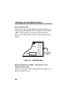
If the PWR LED is not lit:
1.
Make sure that the power is turned on for the device
attached to the TPT.
2.
Disconnect the device to which the transceiver is
attached.
3.
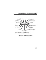
Check the AUI connections for proper pinouts. The
pinouts for the transceiver connection are listed in
Chapter 2.
3.3.3
Connecting the TPT to a Twisted
Pair Segment
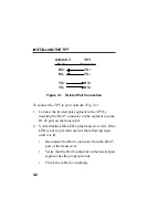
The physical communication link consists of two pairs of
wires; the first pair is the Transmit Pair (TX+, TX-), the
second pair is the Receive Pair (RX+, RX-). The Transmit
Pair of the TPT transceiver connects with the Receive Pair
of an Ethernet device, maintaining polarity. For example,
the positive transmit lead (TX+) of an Ethernet device
goes to the positive receive lead (RX+) of the TPT. The
Receive Pair of the Ethernet device connects to the
Transmit Pair of the TPT. This provides the necessary
Crossover or Null Modem Effect.
Summary of Contents for TPT
Page 2: ......


