3-10
FRX4000 Maintenance G uide, Rev 03
11. Move the motherboard back into position and secure it by
replacing the seven screws. (See
Figure 3-8
on
page 3-8
.)
If you were installing only the connector card, the procedure is
finished. If you are also installing an Expansion card, go to step
12.
12. Remove the new Expansion card from its anti-static bag. (Save
the bag for any future need.)
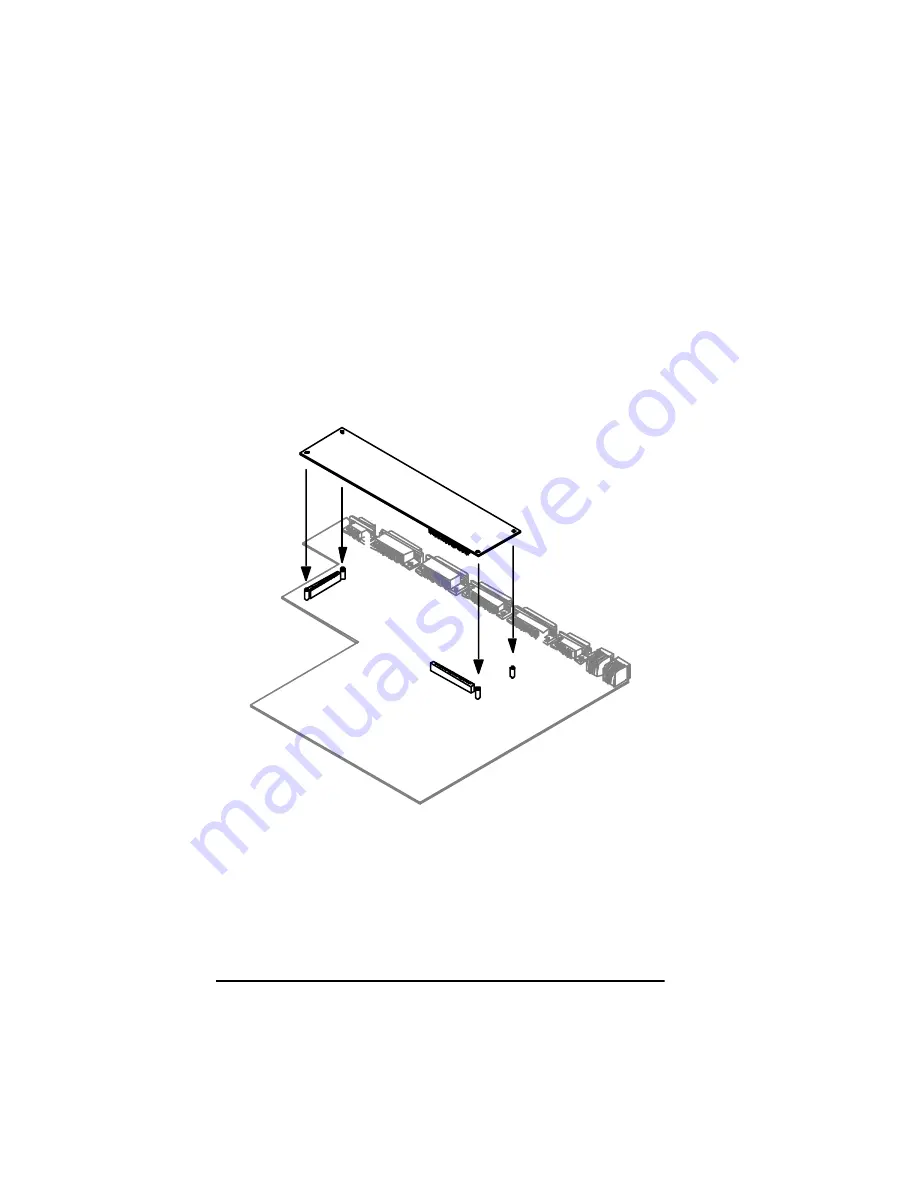
13. Handling the card only by its edges, plug it securely onto the two
motherboard connectors.
Figure 3-11 Installing an Expansion Card
14. Replace the four nylon screws, securing the card to the spacers
on the motherboard.
15. Replace the top by reversing the removal procedure.
Summary of Contents for Netlink FRX4000
Page 1: ...0DLQWHQDQFH XLGH Document number 09 41 06 114 03 The Co mp le te Ne tworkin g S olution TM...
Page 2: ......
Page 6: ...vi FRX4000 Maintenance Guide Rev 03...
Page 12: ......
Page 24: ......
Page 48: ......
Page 58: ......


