Installing the 9C214-3 Power Supply
2-2
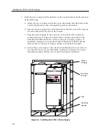
3. Hold the power supply by the handles on the top and bottom of the unit and
do the following:
a. Align the power supply so that the lip on the bottom and the hook on the
top are slightly above the corresponding slots on the chassis.
b. Ease the power supply down until the hook catches the slot on the top and
the tab is inserted in the slot on the bottom.
c. Plug the power supply in the connector on the back of the chassis by
pushing the power supply in until its frame touches the surface of the
SmartSwitch 9000 chassis. Do not force the power supply in place. If
significant resistance is encountered before the frame is flush with the
chassis, remove the power supply, realign it, and push it in again.
d. Secure the power supply to the chassis by tightening the two screws on
the top and two screws on the bottom of the power supply. For proper
chassis grounding, the four screws must be properly tightened.
Figure 2-1. Installing the 9C214-3 Power Supply
2
1
.
.
.
.
.
.
.
.
.
.
.
.
.
.
.
.
.
.
.
.
.
.
207-264v-12A
50-60 Hz
9C214-3
100%
50%
0%
Load
POWER SUPPLY MODULE
STATUS
P
W
R
S
N
B
Securing
Screws
Slot on
Chassis
Tab
Securing
Screws
Summary of Contents for 9C214-3
Page 1: ...9032529 01 SmartSwitch 9000 9C214 3 AC Power Supply Installation Guide...
Page 2: ......
Page 6: ...Notice iv...
Page 8: ...Contents vi...
Page 14: ...Introduction 1 6...
Page 18: ...Installing the 9C214 3 Power Supply 2 4...
Page 26: ...Specifications 4 4...


