Introduction
1-4
Power Distribution System
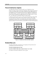
The SmartSwitch 9000 uses a distributed DC power distribution system
(Figure 1-2) similar to those used in super computers. Three separate power buses
are used to distribute DC power. The 48-volt DC System Power Bus, located on
the backplane, powers all modules and the system cooling fans. The Diagnostic
Power Bus provides 5 volts DC to all of the system’s diagnostic controllers and
the Environmental Module. The INB Termination Power Bus provides 3.3 volts
DC to the SmartSwitch 9000 INB termination modules (ITM).
To offer the greatest variety of power options, the 48-volt DC System Power Bus
and all components that use this bus are capable of operating using voltage
ranging from 40–60 volts DC. This capability allows the SmartSwitch 9000 to
operate from typical AC power and to charge batteries in a battery backup unit or
operate on DC power, such as found in a central office or a battery backup system.
Figure 1-2. Distributed DC Power Distribution System
Related Manuals
The manuals listed below should be used to supplement the procedures and
technical data contained in this manual.
SmartSwitch 9000 Installation Guide
SmartSwitch 9000 9C300-1 Environmental Module User’s Guide
In addition, each Interface Module has a user’s guide.
207 - 264 volts
AC Power Supply
56 volts
5 volts
3.3 volts
INB
AC Power Supply
56 volts
5 volts
3.3 volts
INB
DC/DC
Convertor
Diagnostic
Controller
Communications
Systems Components
DC/DC
Convertor
Diagnostic
Controller
Communications
Systems Components
48 Volt System Power Bus
5 Volt Diagnostic Power Bus
207 - 264 volts
3.3 Volt INB Termination Power Bus
Summary of Contents for 9C214-3
Page 1: ...9032529 01 SmartSwitch 9000 9C214 3 AC Power Supply Installation Guide...
Page 2: ......
Page 6: ...Notice iv...
Page 8: ...Contents vi...
Page 14: ...Introduction 1 6...
Page 18: ...Installing the 9C214 3 Power Supply 2 4...
Page 26: ...Specifications 4 4...

