background image

A-10

cab Produkttechnik GmbH  & Co KG / Tharo Systems, Inc.

ZZ

Z1 Z2

ZZ

Z1 Z2

ZZ

Z1 Z2

ZZ

Z1 Z2

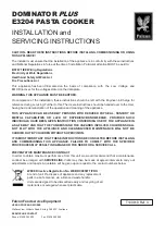
Enter the character  ZZ : 1. input [Z1] - 2. input [ALT-Z2]

Example :

enter "ñ" : 1. input [~] -  2. input [ALT-n]

NOTICE !
Use the data of the table A-3 a to enter the character Z1 if necessary.

Table A-3 b Special characters, which are available by entering two

characters one after another via external keyboard

Summary of Contents for A8

Page 1: ...Edition 2 01 Transfer Printer A8 Operator s Manual ...

Page 2: ...ue modifiables sans prévais Gesellschaft für Tharo Systems Inc Computer und Automations 2866 Nationwide Parkway Bausteine mbH Co KG P O Box 798 cab Produkttechnik GmbH Co KG Brunswick OH 44212 0798 Postfach 1904 D 76007 Karlsruhe Web http www tharo com Wilhelm Schickard Str 14 D 76131 Karlsruhe E mail tharo tharo com Telefon 49 0 721 66 26 0 Tel 1 330 273 4408 Telefax 49 0 721 66 26 249 Fax 1 330 ...

Page 3: ...anual All rights reserved including those of the translations No part of this manual nor any translation may be reproduced or transmitted in any form or by any means for any purpose other than the purchaser s personal use without the express written permission of cab Produkttechnik GmbH Co KG Karlsruhe Edition 2 01 Printed in Germany ...

Page 4: ...Cut Peel off Adapter 15 PC Memory Card 15 External Keyboard 15 Label Design Software EASYLABEL for Windows 15 Print Media 16 Print Media for Direct Thermal Printing 17 Print Media for Thermal Transfer Printing 17 Label Tag Media Specifications 18 Transfer Ribbon 19 2 General Safety Instructions 20 3 Unpacking 20 Delivery Contents 20 Removing the Securing Devices 21 4 Printer Component Location 22 ...

Page 5: ...em Mode MONITOR MODE ASCII Dump Mode 47 System Mode LABEL FROM CARD 48 System Mode ENTER DATA 49 9 Setup 50 Start of Setup Mode 50 Overview of the Setup Parameters 51 Country Land 52 Transfer Print 54 Label Sensor 55 Interface 56 Cut Position 58 Peel Position 59 Printhead Position 60 Heat Level 62 Printer Info 63 Set Date 64 Set Time 65 Character Set 66 Format Memory Card 67 Copy Memory Card 68 Ba...

Page 6: ... Installation of the Cut Peel off Adapter 91 Memory Cards 92 Preparing the Memory Card 92 Installation of the Memory Card 93 Formatting the Memory Card 94 Writing on the Memory Card 94 Printing from the Memory Card 95 External Keyboard 96 Connection the External Keyboard 96 Key Assignment 97 Special Key Functions 97 Appendices Appendix A Character Tables A 1 Setup Selectable Character Tables A 1 U...

Page 7: ...tream Inc TrueType is a registered trademark of Apple Computer Inc Appendix C Error Messages Problem Solution C 1 Error Messagages C 1 Correctable Errors C 1 Irrecoverable Errors C 2 Error Messages during System Test C 2 List of Error Messages C 3 Problem Solution C 7 Appendix D Maintenance Cleaning Adjustment of the Printhead D 1 General Cleaning D 1 Cleaning the Media Feed Roller D 1 Cleaning th...

Page 8: ...ng specifications Furthermore comments on possible error messages and printer maintenance are included Note the directions for use on recommended material and comments on maintenance in order to avoid damage and premature failure of your A8 Every effort has been made in the creation of this manual to provide as much information as possible in an understandable manner We welcome your comments and s...

Page 9: ...reign objects on the labels in order to avoid stratching or abrasion of the printhead This way the printhead might be damaged 3 Use proper label material with a smooth surface only A rough surface will affect the printhead and may cause damage and reduce its operating life 4 Clean the printhead regularly with a special printhead cleaning pen or an isopropyl alcohol soaked cotton swab 5 Print with ...

Page 10: ...s possible to print and to enter variable data without any connection with a computer The printer has at one s disposal five Bitmap and three Speedo fonts internally Besides it is possible to load True Type fonts The use of scaleable fonts and their flexibility in width and height allows exceptional flexibility in label design to suit any requirements Additional printing features include reverse i...

Page 11: ...er disadvantageous circumstances the operation of these devices may cause interference with radio or TV reception which has to be eliminated by the operator WARNING This is a Class A product In a domestic environment this product may cause radio interference in which case the user may be required to take adequate measures Instructions for the Lithium Battery The PCB of the A8 is equipped with a Li...

Page 12: ...hangeable Bitmap fonts Width and height 04 to 1 in 1 3 mm Width and height are selectable up to 10 Font style Revers bold italic underlined mirror inverted outlined grey Font rotation Bitmap fonts and Barcodes 0 90 180 270 Scaleable fonts optional texts in circular format Graphic elements Line box circle ellipse fill in segment arrow Graphic file type PCX IMG BMP TIF GIF and MAC files Bar codes on...

Page 13: ... Adhesive labels 60 160 g sqm Tag Stock up to 180 g sqm Material width 9 in 230 mm Label width 1 to 8 6 in 51 220 mm Label length 2 to 47 in 5 1200 mm Core diameter 3 in 76 mm Supply roll diameter up to 8 in 200 mm Labels may be wound face in or face out on the roll Material recognition Gap sensor see through Bottom reflective sensor Distance to paper edge 12 to 2 in 3 bis 52 mm Transfer ribbon Le...

Page 14: ...e been printed or only at the end of a print job The cutter is powered and controlled directly by the peripheral connector of the A8 For cutter operation the firmware of the A8 will automatically backfeed the label so that after cutting the label roll will be repositioned for the print of the next label Control panel 4 Function keys with LED display lighting up graphic LCD display LCD can be set t...

Page 15: ...a label will only be printed if it is required cut peel off on demand PC Memory Card A8 includes an option for using memory cards in order to permanently store graphics fonts or whole label formats The data can be downloaded via interface PCMCIA 2 1 conforming sRAM cards or Flash EPROM cards are accepted The maximum capacity for A8 is 32 MegaByte Using a memory card the printer can be operated wit...

Page 16: ... wide range of opportunities for usage The A8 is able to print on labels and continuous paper with a maximum supply roll diameter of 8 in 200 mm The minimum core diameter is 3 in 76 mm The printer can also process fanfold label material The ability of label edge recognition which guarantees the precise position of the printer output is accomplished by a moveable photocell This sensor is controlled...

Page 17: ... of the labels should be very smooth to avoid a sandpaper effect on the printhead 3 Always choose material which can be printed on with the lowest possible heat level The greater the heat level the shorter the life of the printhead Moreover with highest heat levels the phases of heating up and cooling down extend This may have a negative effect on the print quality especially if a high print speed...

Page 18: ...ts Item MINIMUM MAXIMUM A Label width 2 51 8 6 220 B Width of silicon liner 2 51 8 6 220 C Label length 2 5 47 2 1200 D Gap between labels 08 2 47 2 1200 E Label thickness 0024 06 01 25 F Thickness of silicon liner 0024 06 01 25 G Distance of the first printing position from the edge of the silicon liner 1 2 5 H Distance of the label sensor from the edge of the silicon liner 12 3 2 52 I Width of p...

Page 19: ...head All of these effects contribute to poor print quality We have carried out numerous tests with many different ribbons and we recommend you use transfer ribbons made by well known brand manufacturers only Depending on the label material several transfer ribbons may be suitable The quality of print is determined by the right combination of these materials NOTICE When choicing the materials make ...

Page 20: ...r to any moisture or use in damp or wet areas The printer will operate with the cover open if necessary This is not recommended asmoving or rotating parts become accessible Keep long hair jewelry loose clothes away from the moving parts During the print process the printhead will become hot Use extra caution when touching the printhead 3 Unpacking Delivery Contents Inspect the A8 packaging and con...

Page 21: ...A8 on a firm surface and remove the securing devices 1 3 2 4 5 Fig 3 Removing the securing devices 1 Open the cover 2 Loosen the knurled knob 2 attached to the plate 1 3 Remove the foam rubber pieces 3 5 which are securing the printhead unit 4 NOTICE Do not touch the printhead with your hands ...

Page 22: ...ttechnik GmbH Co KG Tharo Systems Inc Fig 4a Front view 4 Printer Component Location 1 Display 2 Function keys with indicator LEDs 3 Cover 4 Printhead 5 Ribbon shield 6 Tear off plate 7 Peripheral port 1 2 3 7 6 4 5 ...

Page 23: ...H Co KG Tharo Systems Inc 5 4 3 2 1 6 7 9 8 Fig 4b Side view with cover open 1 Ribbon take up hub 2 Ribbon supply hub 3 Plate 4 Swing arm 5 Media hub 6 Flange 7 Internal rewinder 8 Clamp 9 Media assist bar 10 Print mechanism 10 ...

Page 24: ... ribbon 3 Printhead lever 4 Knurled screw 5 Media stud 6 Rewind guide axle 7 Media guide 8 Label edge sensor 9 Label edge sensor adjustment strut 10 Rewind assist roller 11 Knurled screw 12 Media feed roller 13 Tear off plate 14 Ribbon shield 15 Printhead support 16 Tappet to adjust the printhead support 17 Thermal printhead 2 1 9 10 11 13 12 5 4 7 8 14 15 6 16 3 17 ...

Page 25: ... 10 9 1 Memory card module slot 2 Parallel interface port 3 Serial interface port 4 Connection for the external keyboard 5 Input voltage selector Fuse holder 6 Input voltage selector cover 7 Power switch 8 Power supply connector 9 Internal rewinder 10 Slot for fanfold paper 6 7 8 ...

Page 26: ...the A8 in a special mode to create small printer networks without a RS 485 interface at the computer Further information on this matter is given in appendix F In addition to the serial port the A8 also provides a parallel Centronics interface with a 36 pin interface connector 1 The Centronics interface is always active Any settings in the Setup are not necessary Select the required interface setti...

Page 27: ...ge in the accessories package Slide the voltage selector back into the power supply module so that the correct voltage is visible in the lid window of the cover 2 Connect the printer to a grounded outlet using the power cable supplied in the accessories package 5 1 5 1 Voltage selector 2 Voltage selector cover 3 Power switch 4 Power supply connector 5 Fuses Connection to Power Supply The A8 is des...

Page 28: ...f the display is not showing anything after switching on the printer please check the following whether the connection of the power switch is correct the setting of the voltage selector corresponds with the power supply voltage the fuses in the voltage selector are not defective If all these conditions are true and the device nevertheless cannot be switched on call for service please CAUTION If th...

Page 29: ...e rewound internally To operate in this mode the tear off plate must be replaced by the rewind guide plate 4 5 1 Loosen the knurled screw 3 completely 2 Remove the tear off plate 1 out of the holes 5 in the center mounting plate of the printer 3 Slide the rewind guide plate 2 with the bolts 4 into the holes 5 in the mounting plate Secure the rewind guide plate with the knurled screw 3 at the threa...

Page 30: ...bH Co KG Tharo Systems Inc 1 2 3 4 5 Loading Labels Fig 6 b Loading labels for the tear off mode 1 Open the cover 2 Loosen the knurled screw 11 and remove the flange 10 from the media supply hub 6 6 7 8 9 10 15 14 13 12 11 16 ...

Page 31: ...thead by rotating the lever 1 clockwise until it stops 8 Swing the plate 4 downwards 9 Unroll a length of label stock from the media roll and feed it through the printer as shown in figure 6b The solid line represents the feed path of outside rolled labels the broken line of inside rolled labels The broken dotted line shows the media path of fanfold paper 12 NOTICE It is particularly important to ...

Page 32: ... plate 17 to the internal rewinder 20 Attach the label strip with the clamp 19 in the grooves on the axle of the internal rewinder 20 To tighten the media rotate the rewinder counterclockwise Slide the media guide 18 against the edge of the media strip 14 In case of using the printer with one of the options Present sensor Cutter or External rewinder the label loading is a little different See chap...

Page 33: ... roll and turn the knurled knob 7 clockwise until it stops That way the roll 6 will be attached at the ribbon supply hub 8 5 Slide an empty cardboard core 11 onto the ribbon take up hub 10 and attach it by turning the knurled knob 9 clockwise 6 Feed the transfer ribbon along the path as shown in figure 6d then attach it to the core 11 using adhesive tape or label 7 Turn the take up hub 10 counterc...

Page 34: ...gnized by the photocell The position of the sensor is marked by a notch in the sensor holder If using labels with an unconventional shape i e round or curved the sensor should be positioned at the front edge of the label Adjust the sensor position as follows 1 To lift the printhead turn the printhead lever 1 clockwise until it stops 2 Swing the plate 3 downwards 3 Shift the label edge sensor 4 by ...

Page 35: ...he ribbon should be made even from the left to the right by slanting the axle 2 1 Loosen the adjustment screw 3 2 The axle may be slanted by moving the adjustment screw 3 as required inside the adjustment slot 4 Moving it to the bottom will tightened the ribbon on the inner edge Moving it to the top will tighten the outer side of the transfer ribbon To reduce the formation of wrinkles the ribbon m...

Page 36: ...n carried out during printing 1 The current position of the printhead support 4 is shown at the scale 1 At the tappet 2 is a color mark The figures at the scale are not in reference to an exact value of the label width They should serve as guideline data 2 When using wide labels the position 1 is recommended In this case the printhead support 4 is total deactivated 3 When using narrow labels the t...

Page 37: ...erator with the actual information concerning the current printer mode and label processing The LEDs support the information shown in the display by indicating which keys have to be pressed e g in the event of a fault On the following pages you will find descriptions of the system modes of the A8 the related indications by the LCD display and the LEDs as well as a description of the function keys ...

Page 38: ...splay shows the version of the printer A8 The bottom line of the display shows the numbers 123456 one after the other dependent on the progress of the several test steps LED Display All LEDs flash during initialization once briefly Function Keys ONL key By pressing this key until the end of the system test switch into the system mode TEST PRINT FF key By pressing this key until the end of the syst...

Page 39: ... parameter Pause reprint is on ONL key Pressing both keys together for at least 5 seconds will switch into the SETUP mode CAN key LED ONL off System Mode ONLINE The printer is switched ON and ready to receive data Display The top line of the display shows ONLINE The bottom line of the display shows the time of day During the transfer of data a rotating symbol appears in the right hand corner of th...

Page 40: ...d and formats are stored on it PSE key Display shows current printer mode Printer info see also chapter 11 Table 8 c Function keys in the system mode OFFLINE System Mode OFFLINE The printer is not ready to print or to receive data The status of the printer may be requested Display The top line of the display shows OFFLINE By repeatedly pressing the PSE key the status of the printer will be shown s...

Page 41: ...rinted labels During the transfer of data a rotating symbol appears in the right hand corner of the lower display line LED Display LED ONL on Function Keys CAN key short press Cancels the current print job less than one second Switch to the next job which is available in the input buffer longer press Cancels the current print job greater than one second Clears the input buffer LED CAN blinks Switc...

Page 42: ...eading edge of the next label to be printed is in print position CAN key short press Cancels the current print job less than one second Switch to the next job which is available in the input buffer longer press Cancels the current print job greater than one second Clears the input buffer LED CAN blinks Switch into ONLINE mode LED ONL on PSE key Continues the current print job Switch into PRINT mod...

Page 43: ...emaining labels is shown alternately LED Display LED CAN on LED PSE is flashing Function Keys CAN key short press Cancels the current print job less than one second Switch to the next job which is available in the input buffer longer press Cancels the current print job greater than one second Clears the input buffer LED CAN blinks Switch into ONLINE mode LED ONL on PSE key Continues current print ...

Page 44: ...rint run Display The symbol appears in the display and the type of the fault is shown LED Display LED CAN is flashing Function Keys CAN key Cancels the current print job Switch into ONLINE mode LED ONL on LED CAN off LED PSE off If ONLINE mode cannot be entered switch the printer on and off If the fault remains call for service Table 8 g Function keys in the system mode FAULT IRRECOVERABLE ...

Page 45: ...rrent print requirements for details see chapter 9 Display Following the completion of the system test the display briefly shows SET UP followed by Land or Country Depending on the selection all of the setup parameters and their settings will be shown LED Display All LEDs off Function Keys ONL key Stores the chosen settings of the setup parameters and completes the SETUP mode i e switch into ONLIN...

Page 46: ...n until the system test is completed Following an internal test sample will be printed for details see chapter 10 Then the system test will be repeated Display Following the completion of the system test the display shows Test print LED Display LED ONL on Function Keys CAN key Cancels the test print Switch into SYSTEMTEST mode Table 8 i Function keys in the system mode TEST PRINT ...

Page 47: ...is mode the control codes received by the printer are directly printed as text corresponding to the set font rather than being interpreted as defined by the programming see chapter 12 Display After the completion of the system test the display shows ASCII Dump Mode LED Display LED ONL on Function Keys ONL key Switch into ONLINE mode FF key Initiates a paper feed of about 8 in 21 mm Table 8 k Funct...

Page 48: ...E mode press the key to enter the LABEL FROM CARD mode In this mode the labels stored on the card can be selected to print For files with a variable number of labels the quantity of labels to be printed can be set Display The top line of the display shows Label from card The bottom line of the display shows the file name of the first label file in the list stored on the card After the requested la...

Page 49: ...to the PRINT mode System Mode ENTER DATA This system mode is entered when it is necessary to input varied data during preparing a print job It is possible to input the data via control panel of the A8 as described earlier But it is easier to enter the data by using an external keyboard More information on this subject can be found in chapter 13 Display In the first line appears the name of the inp...

Page 50: ...he first of the parameters to select from Depending on the selection the setup parameters and their settings will be shown The list of parameters is brought up in a row and may be run through repeatedly Each time a parameter setting has been changed there will be a request for confirmation There will not be a general request before leaving the setup mode NOTICE The setup mode can be left at any po...

Page 51: ... position 7 Printhead pos 8 Heat level 9 Printer Info 10 Set date 11 Set time 12 Character set 13 Format card 14 Copy memory card 15 Backfeed 16 Debug mode 17 Tear off pos 18 Pause reprint 1 Country Scrolling up down the parameters Definition of the list item No Para No Item number Para Name of the parameter Parameter may be altered via software software Parameter is limited changeable via softwar...

Page 52: ...printout can be altered via software The language that the prompts on the LCD are displayed in cannot be altered through software only with the front panel Default Setting USA 2 Transfer print Fig 9 b Set Country parameter 18 Pause reprint 1 Country Selection xxxx xxxxxxxxx Yes xxxx xxxxxxxxx No Confirmation Land Deutschland Pays France Country United Kingdom Country USA Pays Suisse Pays Belgie Ma...

Page 53: ...ance 02 06 1999 15 56 56 Country United Kingdom 02 06 1999 15 56 56 Country USA 06 02 1999 03 56 56 pm Land Schweiz 02 06 1999 15 56 56 Pays Suisse 02 06 1999 15 56 56 Pays Belgie 02 06 1999 15 56 56 Maa Suomi 02 06 1999 15 56 56 Nazione Italia 02 06 1999 15 56 56 Pais España 02 06 1999 13 56 56 Zeme Ceska republika 02 06 1999 13 56 56 Land Danmark 02 06 1999 13 56 56 Table 9 Specific format setti...

Page 54: ...r heat level compared to the direct thermal printing mode On the other hand the ribbon sensor is only active in thermal transfer printing mode NOTICE This parameters can also be changed via software For different print jobs it is recommended that you carry out all changes in the software Default Setting Transfer print ON Transfer print On Transfer print Off Transfer print xxx Yes Transfer print xx...

Page 55: ...pre printed continuous paper the label edge can also be recognized through reflective marks on the bottom side of the material see chapter Label Tag Media Specifications NOTICE This parameter can also be changed via software For different print jobs it is recommended that you do the changes in the software Default Setting Gap sensor Fig 9 d Set Label sensor parameter Label sensor Gap sensor Label ...

Page 56: ...connection to transfer data via a long distance requires an appropriate interface on the computer RS 485 Serial connection for network requires an appropriate interface on the computer RS 232 485 Host make it possible to install a RS 485 network with several A8 or Apollo printers via RS 232 interface of the PC Additional to the selection Centronics The parallel interface in addition to the selecte...

Page 57: ...e 3 Label sensor 4 Interface 5 Cut position Baud rate 1 200 Baud rate 230 400 Baud rate 1 200 Baud rate Baud rate 230 400 Baud rate 1 200 Network address A Network address Z Network address Protocol Protocol RTS CTS Protocol XON XOFF Protocol Protocol Protocol XON XOFF Network address A Network address Z Network address Protocol Protocol Protocol RTS CTS Protocol XON XOFF Baud rate Baud rate 115 2...

Page 58: ... that means there is a greater distance between the cutting edge and the rear edge of the label NOTICE It is recommended to carry out changes for different print jobs in the software e g if the cut is not wanted in the middle of the gap The software provides a second value for individual adjustments Any front panel value and software command value are totaled together for printing The current fiel...

Page 59: ... 9 mm If the peel position value is positive the label will be removed further leaving a smaller portion sticking on the liner The setting of this parameter will affect the parameter Tear off Position If this function is active an additional feed forwards take place after completion the print job This makes it possible to cut off the last label at the tear off plate If the value of the peel positi...

Page 60: ...ference value This limitation is necessary to guarantee the printing of the whole label The setting of a negative X offset value shifting the print image inward is not possible Y Offset With this parameter the location of the print image can be shifted in the direction of the label path range from 39 to 39 or 9 9 mm to 9 9 mm When the offset values are positive the printing in the direction of the...

Page 61: ...os Y 9 y mm Printhead pos Y 0 y mm Printhead pos Y y 9 mm Printhead pos Y y 0 mm Printhead pos Y y y mm Yes Printhead pos Y y y mm No Confirmation y offset Sign or y offset 1 10 mm y offset mm Fig 9 h Set Printhead Position parameter Printhead pos X 9 x mm Printhead pos X 0 x mm Printhead pos X x 9 mm Printhead pos X x 0 mm x offset 1 10 mm x offset mm ...

Page 62: ...d the setting possibly has to be adjusted NOTICE To adjust the printer to current print jobs it is recommended to alter the heat level parameter via software e g for different material and speed Any front panel value and software command value are totaled together for printing The current field to be changed is flashing in the display Fig 9 i Set Heat level parameter Heat level x Heat level x Heat...

Page 63: ...vides information about the firmware Furthermore information about the cumulative length of printed media as well as the number of operating hours are shown 8 Heat level 9 Printer info 10 Set date Printer info Printer info Version xxxxxxx Printer info xxxxxx m xxxx h Fig 9 k Printer info display ...

Page 64: ...cember 31 2069 If an invalid date entry is made the display shows Invalid input After pressing the key the parameter may be set again Date changes in the software will only influence the date on the printout but not affect the system date as stored in the setup The current field to be changed is flashing in the display 10 Set date 11 Set time Day Month Year Confirmation Set date xx 12 xxxx Set dat...

Page 65: ...ce the printout but not affect the system time of the printer The changed time will neither be shown in the display nor be stored in the printer setup The current field to be changed is flashing in the display Hour Minute Second Confirmation Set time xx 59 xx Set time xx 00 xx Set time xx xx 59 Set time xx xx 00 Set time 23 xx xx Set time 00 xx xx Set time xx xx xx Yes Set time xx xx xx No Fig 9 m...

Page 66: ...cter set xxxxxxx Yes Character set xxxxxxx No Confirmation Character set Windows 1252 Character set Windows 1250 Character Set Before starting to operate the A8 the Character set of the printer should be adapted to the character set of the computer Adjustment via software is not possible however for characters which are not included in the selected fonts the Unicode character table can be used The...

Page 67: ...2 Character set 13 Format card 14 Copy memory card Format card No Format card Yes Format card xxxx yyyy OK Fig 9 o Delete Format a memory card It will take several seconds to delete files and format a high capacity memory card During this time the symbol is shown in the right hand corner of the display If the procedure has been started without having a card installed the display will show No card ...

Page 68: ...on is carried out file by file This allows the usage of memory cards with different capacities When the duplicate card cannot store any more information the display shows Card full If data with a capacity of more than 1Megabyte has to be copied the duplication process will be divided into several cycles Alternately the printer display will ask to insert either the source card or the destination ca...

Page 69: ... performed if the front label is in its cut and peel position and the A8 has not yet received all of the data for printing the following label Otherwise the print of the second label will be started but only completed after the first one has been picked up Smart backfeed can cause flaws in the printed image NOTICE If the printer will be operated with the setting smart there can be a small white ga...

Page 70: ...g mode parameter 15 Backfeed 16 Debug mode 17 Tear off pos Debug Mode The Debug mode represents a tool for the firmware programmer It will help to recognize faults and their possible sources beyond standard error messages For standard use of the printer the parameter should always be switched OFF Default Setting Debug mode OFF Debug mode Off ...

Page 71: ...f position is active an additional feed forward will take place after completion of the print job This makes it possible to tear off the last label at the tear off plate After starting a new print job first the label material will be fed back until the front edge of the first label is located at the print line If the parameter is OFF the label dispense stops immediately after the last label has co...

Page 72: ...tion Fig 9 t Set Pause Reprint parameter 17 Tear off pos 18 Pause reprint 1 Country Pause reprint On Pause Reprint After completion of a print job the print of the last label may be repeated by pressing the key This function may be switched ON or OFF in the Pause reprint parameter of the setup mode Default Setting Pause Reprint ON ...

Page 73: ...ompleted The display shows Test print and the A8 will print an internal test sample which contains a variety of information about the configuration of the printer as well as the results of the internal test The test printout can also include a range of hardware errors which have occurred previously even if they have disappeared again This information is important for service purposes and can only ...

Page 74: ...e Self Test Printout 1 2 4 5 3 Firmware version Setup and Status information Available character sets Test pattern Bar code with test information Fig 10 Self test printout On the following pages you will find detailed information about the contents of the test printout ...

Page 75: ...ult Result of the system test Any errors will be shown coded as four digit hexadecimal numbers see table 10 for fault correction see appendix C Operative time Cumulative operating time of the printer Number of labels Cumulative amount of printed labels Thermal transfer Cumulative length of printed material in thermal transfer mode Thermal direct Cumulative length of printed material in direct ther...

Page 76: ...inthead error 4000 16384 Wrong board revision 8000 32768 Setup invalid For the test result the codes of occurred errors are added up to a four digit hexadecimal number to determine the final test result For example A D converter fault Printhead error Test result 2004 Table 10 Self test Test result error code 3 Bar Code with Test Information This special bar code is designed for use by Technical Se...

Page 77: ...ws errors such as varying print intensity which indicates the printhead being misadjusted or dirty or missing dots causing vertical white lines 4 Available Character Sets No Identifikation No of the font for programming command T Name Name of font used for internal storing Name of command query sequence q CR Type Method of generating the characters see programming of command T Description Font des...

Page 78: ...peatedly pressing the key The printer info display can be exited by pressing the key back into ONLINE mode Definition of the Printer Info Display Fig 11 a Printer info display 1 On the first page the selected serial interface RS 232 RS 422 RS 485 RS232 485Host will be shown Printer Info 1 RS 232 Printer Info 2 9 600 RTS CTS Fig 11 b Printer info display 2 The second page contains information about...

Page 79: ...indicating that there have been no hardware faults y Type of peripheral device 0 Cutter 1 Present sensor 2 Applicator 3 None fitted 4 External print start For example figure 11 d 3 No peripheral device connected z Configuration setting Transfer print Label sensor The value of z results from adding the code numbers for selected settings Transfer print 1 ON 0 OFF Label sensor 8 Bottom Reflect 4 Gap ...

Page 80: ...ot recognize gaps between labels nor control the ribbon feed NOTICE The font used for printouts in monitor mode is suitable to send by facsimile For questions or future reference print and retain one copy of the label format for each label printed Start of Monitor Mode ASCII Dump Mode To start the monitor mode press the key while switching on the printer and keep it pressed down until the system t...

Page 81: ...le of ASCII Dump Mode The following figures show the normal appearance of a printed label and the appearance of the same label when its commands are printed in ASCII Dump mode Fig 12 a Normal label Fig 12 b The same label as above printed in ASCII Dump mode ...

Page 82: ...l material after printing Delivery Contents The rewinder is packed separately from the printer NOTICE Please keep the original packaging in case the rewinder must be returned The following components are included in the package 1 2 4 8 9 1 Rewinder 2 Flange with knurled screw 3 Flange with Phillips screw 4 2 Rewind axle adapter with a diameter of 3 in or 75 mm 5 8 Screws 6 2 Fuses T 1 6 A for use ...

Page 83: ...otating axle is openly accessible Therefore keep long hair loose clothes and jewelry away from the moving parts The rewinder starts operating as soon as it is switched ON Risk of injury from moving parts Set the switch 1 to the required method of rewinding Rewind with the labels on the outer side of the silicon liner Rewind with the labels on the inner side of the silicon liner Selecting the Metho...

Page 84: ...ower module is visible in the lid window 3 To alter the voltage setting open the cover 4 and remove the voltage selector 3 CAUTION If you have changed the operating voltage of the rewinder you need to replace the fuses 230V 2 x T 800mA 115V 2 x T 1 6A By delivery of the rewinder the fuses for the selected voltage are installed The other fuses are supplied in the accessories package Slide the volta...

Page 85: ... 2 of the rewind axle Pay attention to the selected direction of rewinding full line shows the path of outside roll labels 4 Slide the clamp 6 into the gaps of the flange 5 5 Slide the flange 8 with the knurled screw at the rewind axle The side of the flange with the screw must point to the outside 6 Move the flange 8 in such a way that it lays smooth at the label strip The label strip must be mov...

Page 86: ...Phillips screw onto the rewind axle 5 with the collar of the flange facing towards the rewinder casing Secure the flange onto the axle by tightening the Phillips screw 8 4 Slide the cardboard roll 9 onto the rewind adapter mounted on the inner flange 1 5 Slide the flange 2 fitted with a knurled screw onto the rewind axle so that the rewind adapter locates inside the cardboard core 6 Tighten the kn...

Page 87: ...winding use an adhesive strip or a label to affix the end of the strip to the cardboard core The illustration fig 13 f shows the arrangement for rewinding with the label stock on the outside of the silicon liner 9 Position the rewinder in relation to the printer so that the label strip runs cleanly and without hindrance from the printer to the rewinder 10 Switch ON the rewinder at the power switch...

Page 88: ...ent mode through software NOTICE When editing or creating labels in demand mode make sure that the part of the label which lies directly underneath the photocell is only colored black to a maximum of 50 Higher blackening density print may cause malfunctions of the sensor Mounting the Present Sensor 4 5 3 6 7 Fig 13 g Mounting the present sensor The A8 is generally shipped with the tear off plate 1...

Page 89: ...ve the clamp 11 from the internal rewinder 12 4 Feed the label strip past via dispense edge 9 to the internal rewinder 12 5 Attach the label strip with the clamp 11 into the grooves of the internal rewinder 12 6 Rotate the internal rewinder counterclockwise to tighten the paper 7 Slide the media guide 10 to the edge of the label strip 8 Press the key to synchronize the paper running NOTICE If you ...

Page 90: ...ig 13 i Connectors of the cut peel off adapter Fig 13 k 9 pin SUB D connector of the cut peel off adapter By using the cut peel off adapter it is possible to operate the A8 with cutter assembly or present sensor in a special mode where the print of one label can be started by an external start signal In the peel off mode after removing a label from the peel off position the use of the adapter avoi...

Page 91: ...ternal switch Installation of the Cut Peel off Adapter Pin 3 4 Pin 3 4 Transistor outputs of an optocoupler pin3 collector pin4 emitter If the adapter is used with the present sensor the state of the transistor shows the presence of a label in the peel off position If there is a label the transistor is blocked so that no current can flow between the pins CAUTION The current at the pins 3 and 4 has...

Page 92: ... memory cards The maximum memory is 32 MegaByte Preparing the Memory Card 1 2 3 Fig 13 m Write protection Inserting the battery The write protection of the card may be activated or deactivated by shifting the switch 1 located at the front side of the card The interpretation of the setting may be read from an imprint 3 on the back of the card If you want to format the card or write on it switch off...

Page 93: ...card Fig 13 o Connecting side 1 2 NOTICE At the connecting side of the card there are different guides on the top and the bottom which make it impossible to insert the card incorrectly Insert the card 1 that way into the slot 2 that the one rail guide is at the upper and the two rail guide at the lower side of the card ...

Page 94: ...hods to write onto a memory card The easiest way is to write on the card using the card drive of the A8 and transfer the data via interface For saving a label you need to put the label design commands into brackets consisting of Ms commands Ms LBL ABC Command to save a file called ABC J H 100 0 T S l1 0 0 68 71 108 Contents of the file ABC T 10 10 0 3 pt15 Memory card A 1 NOPRINT Ms LBL End of Sav...

Page 95: ...tart printing 5 For labels with a variable number of labels to print the top line of the display shows Number of labels the bottom line shows 00001 with the first figure flashing cursor Using the key and the key the figure at the position of the cursor may be altered By pressing the key the cursor can be moved to the next figure After confirming the last figure the A8 starts to print 6 When it is ...

Page 96: ...ry card from the OFFLINE mode Input data requests as well as data received from the keyboard will be shown in the display of the A8 All MF 2 compatible keyboards with PS 2 plug supporting code set 3 are usable CAUTION The current consumption of the connected keyboard e g a scanner may not exceed 150 mA Connection the external keyboard 2 3 1 Switch OFF the printer 2 Connect the cable 2 of the keybo...

Page 97: ...ee appendix A table A 3b Some of the special characters cannot be shown in the display of the printer In that case the A8 will use a character which looks similar to the required character NOTICE When using a scanner the character set of the scanner has to be the same as used by the A8 Special Key Functions F1 To enter the list of labels stored on the memory card F2 To repeat the print of the last...

Page 98: ...98 cab Produkttechnik GmbH Co KG Tharo Systems Inc This page is intentionally left blank ...

Page 99: ...A 1 cab Produkttechnik GmbH Co KG Tharo Systems Inc Table A 1 a Character Set Windows 1252 Appendix A Character Tables Setup Selectable Character Tables Table A 1 b Character Set Windows 1250 ...

Page 100: ...A 2 cab Produkttechnik GmbH Co KG Tharo Systems Inc Table A 1 d Character Set Codepage 850 Table A 1 c Character Set ISO 8859 1 ...

Page 101: ...A 3 cab Produkttechnik GmbH Co KG Tharo Systems Inc Table A 1 f Character Set Macintosh Table A 1 e Character Set EBCDIC ...

Page 102: ...A 4 cab Produkttechnik GmbH Co KG Tharo Systems Inc Table A 1 h Character Set ISO 8859 8 Table A 1 g Character Set Codepage 852 ...

Page 103: ...A 5 cab Produkttechnik GmbH Co KG Tharo Systems Inc Unicode Tables Table A 2 a Unicode 0000 00FF ...

Page 104: ...A 6 cab Produkttechnik GmbH Co KG Tharo Systems Inc Table A 2 b Unicode 0100 01FF ...

Page 105: ...A 7 cab Produkttechnik GmbH Co KG Tharo Systems Inc Table A 2 c Unicode 2000 20FF ...

Page 106: ...A 8 cab Produkttechnik GmbH Co KG Tharo Systems Inc Table A 2 d Unicode 2100 21FF ...

Page 107: ... a Special characters with reference to different country settings which are available with the ALT key of the external keyboard Keys of the numeric keyboard GR Deutschland BE Belgie FR France SU Suomi UK United Kingdom IT Italia US USA SP España SG Schweiz DK Danmark SF Suisse CZ Ceska republika Character Character ALT key ...

Page 108: ... Z2 Enter the character ZZ 1 input Z1 2 input ALT Z2 Example enter ñ 1 input 2 input ALT n NOTICE Use the data of the table A 3 a to enter the character Z1 if necessary Table A 3 b Special characters which are available by entering two characters one after another via external keyboard ...

Page 109: ... 485 Host operation Pin 1 Pin 13 Pin 14 Pin 25 Fig B 1 Connector of the serial interface rear of the printer Table B 1 Signals of the serial interface connector Pin Description Function 1 CG Protective Ground 2 TxD Transmit Data RS 232 3 RxD Receive Data RS 232 4 RTS Request to send 5 CTS Clear to send 7 GND Logic Ground 9 TDATA Transmit Data RS 422 RS 485 10 TDATA Transmit Data RS 422 RS 485 18 R...

Page 110: ...t the manufacturer of your computer on the pin assignment of the interface Use the pin assignment of the printer as shown in table B 1 to obtain a suitable cable 25 pin connector 25 pin plug 9 pin connector 25 pin plug 2 2 3 3 5 7 8 20 1 4 4 5 6 Fig B 3 Interface cable with 9 pin computer connector for RS 232 with protocol or XON XOFF Fig B 2 Interface cable with 25 pin computer connector for RS 2...

Page 111: ...6 1 1 2 3 3 2 4 5 5 4 7 7 6 8 20 Interface Cable for RS 422 RS 485 To control the A8 by RS 422 RS 485 interface only the signals TDATA TDATA RDATA and RDATA are necessary Check the pin assignment for the interface of your computer and use the pin assignment of the printer as shown in table B 1 to obtain a suitable cable The connectors of TDATA and RDATA as well as TDATA and RDATA at the plug in co...

Page 112: ...able shown in the figure below can be used for a maximum of three printers 7 9 18 10 19 7 9 18 10 19 25 pin connector 25 pin plug 25 pin plug A8 Apollo 25 pin plug If more than three printers have to be controlled further connectors equal to the bottom 25 pin plug have to be added to the cable For long distance cables or a higher baud rate it is important to terminate the cables when wiring Normal...

Page 113: ...no problems with the external control of the A8 In the event of any difficulties consult the manufacturer of your computer on the pin assignment of the computer s interface Use the pin assignment of the printer as shown in table B 2 to obtain a suitable cable Pin Signal Pin Signal Pin Signal Pin Signal 1 STROBE 10 ACKNLG 19 GND 28 GND 2 DATA 1 11 BUSY 20 GND 29 GND 3 DATA 2 12 PE 21 GND 30 GND 4 D...

Page 114: ...he peripheral port Pin 8 Pin 1 Pin 9 Pin 15 Pin Description Function 1 COD0 Code bit 0 2 PAI0 Sensor bit 0 3 PAO0 Control bit 0 4 PAO2 Control bit 2 5 GND Logic grounding 6 5V Logic voltage Imax 500 mA 7 PGND Power grounding 8 24V Voltage for power level Imax 1 2 A 9 COD1 Code bit 1 10 PAI1 Sensor bit 1 11 PAO1 Control bit 1 12 PAO3 Control bit 3 13 GND Logic grounding 14 PGND Power grounding 15 2...

Page 115: ...e corrected by the operator and also allows you to continue the print job after fault correction Display The symbol appears in the display The display shows alternately the type of fault and the total of the remaining labels of the current print job LED Display LED CAN on LED PSE is flashing Function Keys Table C 1 Function keys in mode FAULT CORRECTABE CAN key short press Cancels the current prin...

Page 116: ... Cancels the current print job Switch into ONLINE mode LED ONL on LED CAN off LED PSE off If ONLINE mode cannot be entered switch printer on and off again If the fault remains again call for Service Table C 2 Function keys in mode FAULT IRRECOVERABLE Error during System Test When switched on the printer automatically performs an internal self test If the test is completed succesfully the A8 procee...

Page 117: ... the extreme thickness of the material Cutter cannot return into its home position and stays in an undefined position Error of the option Cutter The cutter is unable to cut the labels due to the extreme thickness of the material but is able to return into its home position Hardware error of the option Cutter Solution Switch printer off and then on If error recurs contact Service Replace battery in...

Page 118: ...arge graphics There are labels missing on the label material Solution Switch printer off and then on If error recurs contact Service Check the contents of the card Switch printer off and then on If error recurs contact Service Lock the printhead Switch printer off and then on If error recurs contact Service After pausing to cool down the printhead the print job will be continued automatically If t...

Page 119: ...he supply roll of transfer ribbon by turning the knurled knob at the supply hub Switch printer off Correct the interface setting in the printer setup see chapter 9 Possible cause The label format as set in the software does not correspond with the real label format Printer is loaded with continuous paper but the software is set on labels Definition of the label size is missing at the label descrip...

Page 120: ...rdware error Refers to the optional memory card Write protection is activated Error during firmware update Firmware version is not valid for the present hardware version Solution Depending on the type of fault the command can be skipped by pressing the key or the print job has to be cancelled by pressing the key There is no solution Check the battery Reformat card Copy backup files onto the card S...

Page 121: ...g Label is not inserted in the label edge sensor Correct the label path chapter 6 Label edge sensor is dirty Clean it Printer is in Monitor Mode ASCII Dump Mode Press the key to cancel this mode Transfer ribbon is wrong inserted Check if the inked side faces the label see chapter 6 The combination of ribbon and media is unsuitable Choose different type of ribbon Setting of the size in the software...

Page 122: ...s Printhead is dirty Clean printhead appendix D Printhead is not correct adjusted Adjust printhead appendix D Faulty adjustment of the printhead support Adjust printhead support see chapter 7 Transfer ribbon is not locked at the supply hub Supply hub does not turn Tighten the ribbon see chapter 6 Problem Vertical white lines in the print image Horizontal white lines in the print image Print image ...

Page 123: ...intenance switch the printer OFF and disconnect it from the power supply General Cleaning While operating dust accumulates especially within the printer mechanism Remove dirt and dust regularly using a soft brush or a vacuum The cover of the A8 may be cleaned using standard cleanser CAUTION Do not use abrasive cleaning powders or solvents Cleaning the Media Feed Rollers Accumulations of dirt on th...

Page 124: ...leaning Recommended cleaning intervalls Direct Thermal Printing each time you change the label roll Thermal Transfer Printing each time you change the ribbon CAUTION Do not use any sharp objects for cleaning the printhead Do not touch the protective glass layer of the printhead Clean the printhead as follows 1 Lift the printhead 2 Remove label material and transfer ribbon from the printer 3 Clean ...

Page 125: ...ge appears uneven from one side to the other Adjust the printhead as follows 1 You may leave the transfer ribbon 1 inside the printer and simply poke through it with your hex wrench 2 Loosen the locking screw 2 on the printhead by half a turn This will allow for the required horizontal adjustment of the printhead 3 By turning the two screws underneath 3 you may shift the printhead as follows By tu...

Page 126: ...ust be closed after every single adjustment step to make the change effective 5 Tighten the locking screw 2 6 Perform a test print for instance a wide black line over the whole width of the label and review the results 7 Repeat steps 2 to 6 as necessary to complete the adjustment ...

Page 127: ...ll of the four function keys at once The display will show SYSTEM UPDATE 3 Transmit the data to the printer Under DOS use the following copy command COPY A8_XXX FMW LPT1 b 4 During processing the printer display indicates the progress with a graphic progress bar After completing the copy process the display shows OK and all LEDs are flashing This also indicates the completion of the up dating Swit...

Page 128: ...E 2 cab Produkttechnik GmbH Co KG Tharo Systems Inc This page is intentionally left blank ...

Page 129: ...llows Type RS 232 485 Host Baud rate optional Protocol RTS CTS Network address optional e g A 5 Configure the interface at all other printers as follows Type RS 485 Baud rate like Printer 1 Net work address optional but different from each other printer e g B C and so on 6 Transmit the data via suitably configured RS 232 interface baud rate must match Printer 1 of the computer 7 Use the command ES...

Page 130: ...F 2 cab Produkttechnik GmbH Co KG Tharo Systems Inc This page is intentionally left blank ...

Page 131: ...onnection serial interface 25f B 1f Control characters for the monitor mode 80 Control panel 14 37ff Correctable errors C 1 Country 52f Cover 22 Cut Peel off adapter 15 90f Cut position 51 58 Cutter 14 Cutter blocked C 3 Cutter jammed C 3 Cutter stuck C 3 D Date 53 64 Debug mode 70 Delivery contents 20 Dimensions 14 Direct thermal printing 17 Display 22 37f Documentation 8 dRAM malfunction C 4 E E...

Page 132: ...ller 24 Media feed roller cleaning D 1 Media guide 32 89 Media hub 23 30f Media loading 29ff Media rewinder external 14 Memory card 15 48 67f 92ff Memory card installing 93 Memory card formatting 94 Memory card module slot 25 93 Memory card writing on 94 Memory card printing from 95 Memory overflow C 4 Method of rewinding external rewinder 83 Monitor mode 80f MONITOR MODE system mode 47 N No label...

Page 133: ...26 56f B 3 RS 485 26 56f B 3 S Securing device 21 See through sensor 13 55 Safety instructions 20 Self test 73ff Self test printout 74 Serial interface port 22 88 90f B 6 Service manual 8 Setup 55ff Setup parameters overview 51 SETUP system mode 45 Slot for fanfold paper 25 Slot for memory card 25 93 Structural error C 6 Switch ON 28 System modes 38ff SYSTEM TEST system mode 38 T Tear off plate 20...

Page 134: ... Transfer Printer A8 Applied EU Regulations and Norms EC Machinery Regulations 89 392 EEC Appendix IIA Machine Safety EN 292 T1 T2 1991 11 EC Low Voltage Regulations 73 23 EEC Data and Office Machine Safety EN60950 1992 A1 1993 EN 60950 A2 1993 EC Electromagnetic Compatibility Regulations 89 336 EEC Threshold values for the Interference EN 55022 1995 05 of Data Machines Interference Resistance in ...

Reviews: