


Page 30 of 106
INSTRUCTION, USE AND
MAINTENANCE MANUAL
GB
KENDO.30LIGHT-KENDO.30LIGHTFI
7105-M002-0_B
Fig. 10
9.3
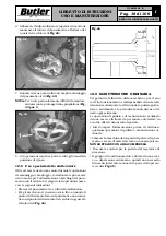
Electrical connection
EVEN THE TINIEST PROCEDURE
OF AN ELECTRICAL NATURE
MUST BE CARRIED OUT BY PRO-
FESSIONALLY QUALIFIED
STAFF.
As envisaged by the regulations in force, the machine is
not equipped with a master circuit breaker, but simply
has a plug-socket connection to the electrical mains.
The machine is supplied with
3
mt. of free cable. A plug
corresponding to the following requirements must be
connected to the cable:
• Conformity to Norm
IEC 309
•
230/400 Volt – 16A
•
2P + Ground
•
IP 44
VERSION WITH
MONOPHASE MOTOR
On delivery, the machine is preset to operate at a voltage
of 200 ÷ 265 V - 50/60 Hz monophase.
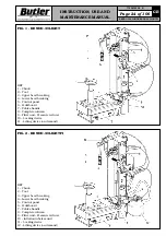
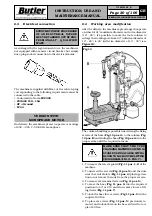
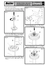
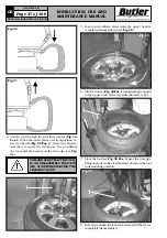
9.4
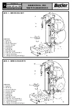
Working area modification
After the delivery, the machine is prearranged to operate
on wheel of 41” maximum diameter and a rim diameter
(10” - 26”). It’s possible to move the tools column to
enlarge the working area from 43” (with rim diameter of
12” - 28”) to 45” (with rim diameter of 14” - 30”) (see
Figure 10
).
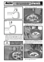
The column handling is possible unscrewing the fixing
screws of the base (
Fig. 10 pos. A
) to the column (
Fig.
10 pos. B
) and sliding the base (
Fig. 10 pos. A
) into the
proper slots until the required measure.
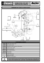
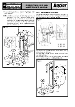
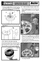
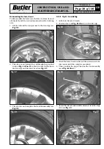
MAKE SURE THAT THE TYRE
CHANGING MACHINE COLUMN IS
STABLE USING A CABLE WITH A
BLOCK TO LOCK ON THE LIFTING
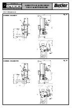
CROSS BEAM (FIG. 11 POS. 7).
1. To remove the lateral guard (
Fig. 11 pos. 1-2
) of the
machine.
2. To unscrew the screws (
Fig. 11 pos. 3
) and the nuts
near the central slots (
Fig. 11 pos. 4
) playing atten-
tion to not remove the nuts from the proper screws.
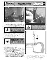
3. To remove six remained screws (
Fig. 11 pos. 5
).
4. To move the base (
Fig. 11 pos. 6
) into the required
position (to 43” or 45”) and if necessary to use a lift-
ing device (
Fig. 11 pos. 7
).
5. To lock the base three screws (
Fig. 11 pos. 3
) with a
couple of 80 Nm.
6. To place six screws (
Fig. 11 pos. 5
) previously re-
moved and to lock them on the base side with a cou-
ple of 80 Nm.


