70
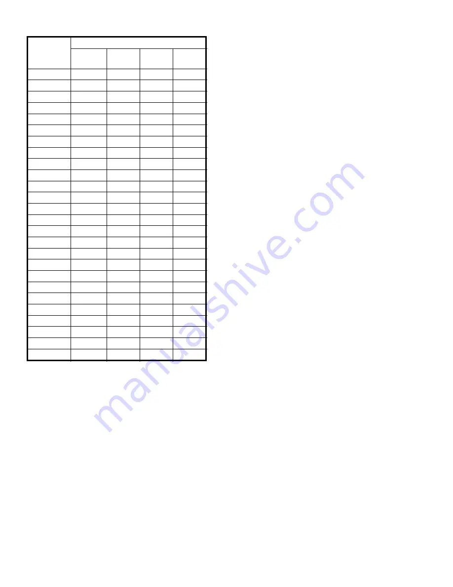
Table 10: Input Rate
(turn adjustment screw counterclockwise to
decrease manifold pressure, or clockwise to
increase manifold pressure).
iii
. Turn on gas valve not having pilot control.
Adjust gas valve pressure regulator to obtain
required manifold pressure. Manifold
pressure may not change during initial turns
of adjustment screw.
3. Clock gas meter for at least 30 seconds. Use Table
10 to determine gas flow rate in Cubic Feet per
Hour.
4. Determine Input Rate. Multiply gas flow rate by gas
heating value.
5. Compare measured input rate to input rate stated on
Rating Label.
a. Boiler must not be overfired. Reduce input rate
by decreasing manifold pressure. Do not reduce
more than 0.3 inch w.c. If boiler is still overfired,
contact your Governale distributor or Regional
Office for replacement Gas Orifice.
b. Increase input rate if less than 98% of Rating
Label input. Increase manifold gas pressure no
more than 0.3 inch w.c. If measured input rate is
still less than 98% of rated input:
i
. Remove Main Burners per procedure in
Section X: Service Instructions.
ii
. Remove gas orifices. Drill one (1) drill size
larger (drill size is stamped on orifice, or see
Key No. 4D in repair parts section).
iii
. Reinstall gas orifices and main burners.
Measure input rate.
6. Recheck Main Burner Flame.
7. Return other gas-fired appliances to previous
conditions of use.
L.
Adjust gas input rate to boiler.
LP/Propane.
1. Set thermostat to highest setting.
2. Adjust tank regulator for gas valve inlet pressure of
13.5 inches w.c. or less.
3. Gas valve has step opening regulator which initially
opens to 1.4 or 2.5 inch w.c. and steps to full
pressure after approximately 30 seconds. Check
manifold pressure after step has occurred. Adjust gas
valve pressure regulator as necessary for 10.0 inches
w.c. (turn adjustment screw counterclockwise to
decrease manifold pressure, or clockwise to increase
manifold pressure). If 10.0 inches w.c. can not be
attained, check gas valve inlet pressure. If less than
11.0 inches w.c., contact gas supplier for assistance.
M.
Clean Heating System (Steam).
A local qualified
water treatment chemical specialist is a suggested
source for recommendations regarding appropriate
chemical compounds and concentrations which are
compatible with local environmental regulations.
1. Oil from new piping connections and sediment in
existing piping must be removed from system to
prevent unsteady water line and carry-over of
entrained water into supply main.
a. Fill boiler to normal waterline.
b. Follow Lighting or Operating Instructions to
place boiler in operation. See Figure 53, 54, 55,
56 or 57.
c. Operate boiler with steam in entire system for
several days to bring system oil and dirt back to
boiler.
d. Drain condensate from drain valve in wet return.
Operate boiler until condensate runs clean.
2. Boil-out boiler.
a. Follow instructions TO TURN OFF GAS TO
APPLIANCE. See Figure 53, 54, 55, 56 or 57.
b. Fill boiler to normal waterline.
c. Remove safety valve.
d. Pour recommended boil-out compound into
boiler through safety valve opening.
e. Reinstall safety valve in Tapping "E" with
spindle in vertical position. See Figures 1 and 2.
s
d
n
o
c
e
S
e
n
O
r
o
f
n
o
it
u
l
o
v
e
R
l
a
i
D
r
e
t
e
M
s
a
G
f
o
e
z
i
S
fl
a
H
-
e
n
O
.t
F
.
u
C
e
n
O
.t
F
.
u
C
o
w
T
.t
F
.
u
C
e
v
i
F
.t
F
.
u
C
0
3
0
6
0
2
1
0
4
2
0
0
6
2
3
6
5
3
1
1
5
2
2
3
6
5
4
3
3
5
6
0
1
2
1
2
9
2
5
6
3
0
5
0
0
1
0
0
2
0
0
5
8
3
7
4
5
9
9
8
1
4
7
4
0
4
5
4
0
9
0
8
1
0
5
4
2
4
3
4
6
8
2
7
1
0
3
4
4
4
1
4
2
8
4
6
1
0
1
4
6
4
9
3
8
7
7
5
1
1
9
3
8
4
7
3
5
7
0
5
1
5
7
3
0
5
6
3
2
7
4
4
1
0
6
3
2
5
5
3
9
6
8
3
1
6
4
3
4
5
3
3
7
6
3
3
1
3
3
3
6
5
2
3
4
6
9
2
1
1
2
3
8
5
1
3
2
6
4
2
1
0
1
3
0
6
0
3
0
6
0
2
1
0
0
3
2
6
9
2
8
5
6
1
1
0
9
2
4
6
9
2
6
5
2
1
1
1
8
2
6
6
9
2
4
5
9
0
1
3
7
2
8
6
8
2
3
5
6
0
1
5
6
2
0
7
6
2
1
5
3
0
1
7
5
2
2
7
5
2
0
5
0
0
1
0
5
2
4
7
4
2
8
4
7
9
3
4
2
6
7
4
2
7
4
5
9
7
3
2
8
7
3
2
6
4
2
9
1
3
2
0
8
2
2
5
4
0
9
5
2
2
Summary of Contents for Independence
Page 4: ... Figure 1 Dimensional Drawing ...
Page 19: ...19 Figure 25 Recommended Water Piping for Circulator Zoned Heating System ...
Page 20: ...20 Figure 25A Recommended Water Piping for Zone Valve Zoned Heating System ...
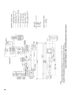
Page 29: ...29 Figure 34 Vent Damper Schematic Wiring Diagram Figure 33 Vent Damper Harness to Limit ...
Page 30: ...30 Figure 35 Wiring Diagrams Steam Continuous Ignition Standing Pilot Probe Low Water Cutoff ...
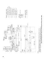
Page 32: ...32 Figure 36 Wiring Diagrams Steam Intermittent Ignition EI Probe Low Water Cutoff ...
Page 34: ...34 Figure 37 Wiring Diagrams Steam Intermittent Ignition HSP Probe Low Water Cutoff ...
Page 36: ...36 Figure 38 Wiring Diagrams Steam Continuous Ignition Standing Pilot Float Low Water Cutoff ...
Page 38: ...38 Figure 39 Wiring Diagrams Steam Intermittent Ignition EI Float Low Water Cutoff ...
Page 40: ...40 Figure 40 Wiring Diagrams Steam Intermittent Ignition HSP Float Low Water Cutoff ...
Page 44: ...44 Figure 42 Wiring Diagrams Water Intermittent Ignition EI Intermittent Circulation ...
Page 46: ...46 Figure 43 Wiring Diagrams Water Intermittent Ignition HSP Intermittent Circulation ...
Page 48: ...48 Figure 44 Wiring Diagrams Water Continuous Ignition Standing Pilot Gravity Circulation ...
Page 50: ...50 Figure 45 Wiring Diagrams Water Intermittent Ignition EI Gravity Circulation ...
Page 52: ...52 Figure 46 Wiring Diagrams Water Intermittent Ignition HSP Gravity Circulation ...
Page 54: ...54 Figure 47 Wiring Diagrams Water Continuous Ignition Standing Pilot Tankless Heater ...
Page 56: ...56 Figure 48 Wiring Diagrams Water Intermittent Ignition EI Tankless Heater ...
Page 58: ...58 Figure 49 Wiring Diagrams Water Intermittent Ignition HSP Tankless Heater ...
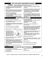
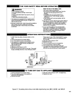
Page 61: ...61 Figure 53 Lighting Instructions Continuous Ignition System VR8200 and VR8300 Gas Valves ...
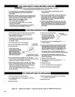
Page 62: ...62 Figure 54 Lighting Instructions Continuous Ignition System 7000 ERHC Gas Valve ...
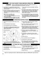
Page 65: ...65 Figure 57 Operating Instructions Intermittent Ignition System HSP SV9501 and SV9601 ...
Page 76: ...76 ...
Page 77: ...77 Honeywell Hot Surface to Pilot Trouble Shooting Guide ...
Page 91: ...91 THIS PAGE LEFT BLANK INTENTIONALLY ...
Page 92: ...92 ...
Page 96: ...96 ...
Page 99: ...99 THIS PAGE LEFT BLANK INTENTIONALLY ...
Page 100: ...100 ...

