9
V.
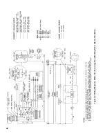
Water Boiler with Intermittent Ignition (HSP) and
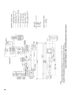
Tankless Heater. See Figure 49.
1. Normal Operation
a. Thermostat calls for heat or low limit senses
water temperature below set point.
b. Vent Damper (if used) opens as stated in Vent
Damper Sequence of Operation.
c
.
Gas Valve is energized. Igniter is energized and
Pilot Valve opens to ignite Pilot Burner.
d. Sensor proves presence of pilot flame and Gas
Valve de-energizes igniter. Main Valve opens
and ignites Main Burners.*
e
.
After Thermostat is satisfied Gas Valve is de-
energized, extinguishing pilot and main flame.
Vent Damper (if used) closes.
2. Safety Shutdown
a
.
Limit: Automatically interrupts main burner
operation when water temperature exceeds set
point. Maximum allowable temperature is 250°F.
Normal operation resumes when water
temperature falls below set point.
b
.
Blocked Vent Switch. Automatically interrupts
main burner operation when excessive vent
system blockage occurs. Control is a multiple
use device. If blocked vent switch is activated do
not attempt to place boiler in operation. Correct
source of blockage and reset blocked vent
switch.
c
.
Flame Roll-out Switch. Automatically interrupts
boiler operation when flames or excessive heat
are present in vestibule. Control is single use
device. If flame roll-out switch is activated do
not attempt to place boiler in operation. Correct
source of blockage and replace flame roll-out
switch.
d
.
Sensor: senses pilot flame and causes Gas Valve
to interrupt main burner and pilot burner gas
flow should pilot burner flame extinguish.
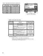
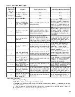
For Hot Surface to Pilot Trouble Shooting Guide, see
Page 75.
*
• SV9500 and SV9600 Gas Valves:
The igniter and pilot gas valve will stay
energized until either the pilot lights or the call
for heat ends.
• SV9501 and SV9601 Gas Valves:
If the pilot fails to light after a 90 second trial for
ignition, the igniter will be de-energized and the
pilot gas valve will close. After a 5 minute delay,
the igniter will be re-energized and the pilot gas
valve will re-open. This continuous retry cycle
will end either when the pilot lights or the call
for heat ends.
Summary of Contents for Independence
Page 4: ... Figure 1 Dimensional Drawing ...
Page 19: ...19 Figure 25 Recommended Water Piping for Circulator Zoned Heating System ...
Page 20: ...20 Figure 25A Recommended Water Piping for Zone Valve Zoned Heating System ...
Page 29: ...29 Figure 34 Vent Damper Schematic Wiring Diagram Figure 33 Vent Damper Harness to Limit ...
Page 30: ...30 Figure 35 Wiring Diagrams Steam Continuous Ignition Standing Pilot Probe Low Water Cutoff ...
Page 32: ...32 Figure 36 Wiring Diagrams Steam Intermittent Ignition EI Probe Low Water Cutoff ...
Page 34: ...34 Figure 37 Wiring Diagrams Steam Intermittent Ignition HSP Probe Low Water Cutoff ...
Page 36: ...36 Figure 38 Wiring Diagrams Steam Continuous Ignition Standing Pilot Float Low Water Cutoff ...
Page 38: ...38 Figure 39 Wiring Diagrams Steam Intermittent Ignition EI Float Low Water Cutoff ...
Page 40: ...40 Figure 40 Wiring Diagrams Steam Intermittent Ignition HSP Float Low Water Cutoff ...
Page 44: ...44 Figure 42 Wiring Diagrams Water Intermittent Ignition EI Intermittent Circulation ...
Page 46: ...46 Figure 43 Wiring Diagrams Water Intermittent Ignition HSP Intermittent Circulation ...
Page 48: ...48 Figure 44 Wiring Diagrams Water Continuous Ignition Standing Pilot Gravity Circulation ...
Page 50: ...50 Figure 45 Wiring Diagrams Water Intermittent Ignition EI Gravity Circulation ...
Page 52: ...52 Figure 46 Wiring Diagrams Water Intermittent Ignition HSP Gravity Circulation ...
Page 54: ...54 Figure 47 Wiring Diagrams Water Continuous Ignition Standing Pilot Tankless Heater ...
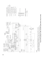
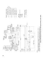
Page 56: ...56 Figure 48 Wiring Diagrams Water Intermittent Ignition EI Tankless Heater ...
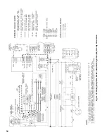
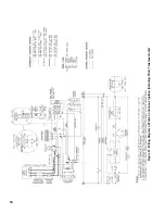
Page 58: ...58 Figure 49 Wiring Diagrams Water Intermittent Ignition HSP Tankless Heater ...
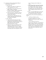
Page 61: ...61 Figure 53 Lighting Instructions Continuous Ignition System VR8200 and VR8300 Gas Valves ...
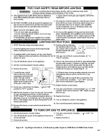
Page 62: ...62 Figure 54 Lighting Instructions Continuous Ignition System 7000 ERHC Gas Valve ...
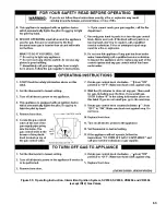
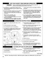
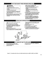
Page 65: ...65 Figure 57 Operating Instructions Intermittent Ignition System HSP SV9501 and SV9601 ...
Page 76: ...76 ...
Page 77: ...77 Honeywell Hot Surface to Pilot Trouble Shooting Guide ...
Page 91: ...91 THIS PAGE LEFT BLANK INTENTIONALLY ...
Page 92: ...92 ...
Page 96: ...96 ...
Page 99: ...99 THIS PAGE LEFT BLANK INTENTIONALLY ...
Page 100: ...100 ...

