27
A.
General.
Install wiring and ground boiler in accordance
with requirements of authority having jurisdiction, or in
absence of such requirements the
National Electrical
Code
, ANSI/NFPA 70 and/or CSA C22.1 Electrical
Code.
B.
Wire Vent Damper
(if used).
1. Steam or Water with gravity circulation or tankless
heater.
a. Remove one (1) 7/8" knockout from junction
box. Carefully remove transformer - avoid undue
strain on wires.
b. Install Vent Damper Harness into top of junction
box.
c. Remove factory installed jumper plug (if so
equipped) from Vent Damper Receptacle. Plug
Vent Damper Harness into Vent Damper
Receptacle. See Figure 31.
2. Water with intermittent circulation and without
tankless heater.
a. Remove 7/8" knockout and cover from limit
control.
b. Install Vent Damper Harness into top of limit.
c. Remove factory installed jumper plug from Vent
Damper Receptacle. Plug Vent Damper Harness
into Vent Damper Receptacle. See Figure 31.
d. Install cable clamp around flexible Vent Damper
Harness. Attach to jacket top panel. See Figure
33.
3. Note: After vent damper is installed and operated
through one (1) cycle, the control circuit will
operate only when vent damper is in control circuit.
C.
Install thermostat.
Locate on inside wall
approximately 4 feet above floor. Do not install on
outside wall, near fireplace, or where influenced by
drafts or restricted air flow, hot or cold pipes, lighting
fixtures, television, or sunlight. Allow free air
movement by avoiding placement of furniture near
thermostat.
VIII. Electrical
Figure 31: Vent Damper Connection Detail
d. Install cable clamp around flexible Vent Damper
Harness. Attach to jacket top panel. See Figure
32.
Figure 32: Vent Damper Harness to Junction Box
R
E
G
N
A
D
r
o
n
o
i
t
a
ll
a
t
s
n
i
g
n
i
t
p
m
e
t
t
a
e
r
o
f
e
b
d
e
r
e
w
o
p
n
u
e
r
a
s
n
o
i
t
c
e
n
n
o
c
l
a
c
i
r
t
c
e
l
e
ll
a
e
r
u
s
s
a
y
l
e
v
i
t
i
s
o
P
l
a
c
i
r
t
c
e
l
e
ll
a
t
u
o
k
c
o
L
.
g
n
i
d
li
u
b
r
o
r
e
li
o
b
e
h
t
f
o
s
n
o
i
t
c
e
n
n
o
c
r
o
s
t
n
e
n
o
p
m
o
c
l
a
c
i
r
t
c
e
l
e
f
o
e
c
i
v
r
e
s
.
f
f
o
d
e
n
r
u
t
s
i
r
e
w
o
p
e
c
n
o
k
c
o
l
d
a
p
h
t
i
w
s
e
x
o
b
G
N
I
N
R
A
W
l
a
c
i
s
y
h
p
s
u
o
i
r
e
s
n
i
t
l
u
s
e
r
y
a
m
r
e
li
o
b
e
h
t
o
t
s
n
o
i
t
c
e
n
n
o
c
l
a
c
i
r
t
c
e
l
e
e
r
i
w
y
l
r
e
p
o
r
p
o
t
e
r
u
li
a
F
.
m
r
a
h
e
r
o
f
e
b
f
f
o
s
i
r
e
w
o
p
ll
a
e
r
u
s
e
k
a
M
.
e
c
r
u
o
s
e
n
o
n
a
h
t
e
r
o
m
m
o
r
f
e
b
y
a
m
r
e
w
o
p
l
a
c
i
r
t
c
e
l
E
.
k
r
o
w
l
a
c
i
r
t
c
e
l
e
y
n
a
g
n
i
t
p
m
e
t
t
a
.
t
c
e
n
n
o
c
s
i
d
d
e
s
u
f
d
e
z
i
s
y
l
r
e
p
o
r
p
a
h
t
i
w
d
e
t
c
e
t
o
r
p
e
b
t
s
u
m
r
e
li
o
b
h
c
a
E
.
s
l
o
r
t
n
o
c
g
n
i
t
a
r
e
p
o
r
o
y
t
e
f
a
s
y
n
a
e
v
i
t
a
r
e
p
o
n
i
e
k
a
m
r
o
t
u
o
p
m
u
j
r
e
v
e
N
Summary of Contents for Independence
Page 4: ... Figure 1 Dimensional Drawing ...
Page 19: ...19 Figure 25 Recommended Water Piping for Circulator Zoned Heating System ...
Page 20: ...20 Figure 25A Recommended Water Piping for Zone Valve Zoned Heating System ...
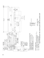
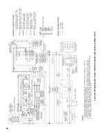
Page 29: ...29 Figure 34 Vent Damper Schematic Wiring Diagram Figure 33 Vent Damper Harness to Limit ...
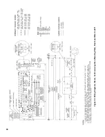
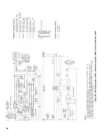
Page 30: ...30 Figure 35 Wiring Diagrams Steam Continuous Ignition Standing Pilot Probe Low Water Cutoff ...
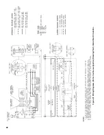
Page 32: ...32 Figure 36 Wiring Diagrams Steam Intermittent Ignition EI Probe Low Water Cutoff ...
Page 34: ...34 Figure 37 Wiring Diagrams Steam Intermittent Ignition HSP Probe Low Water Cutoff ...
Page 36: ...36 Figure 38 Wiring Diagrams Steam Continuous Ignition Standing Pilot Float Low Water Cutoff ...
Page 38: ...38 Figure 39 Wiring Diagrams Steam Intermittent Ignition EI Float Low Water Cutoff ...
Page 40: ...40 Figure 40 Wiring Diagrams Steam Intermittent Ignition HSP Float Low Water Cutoff ...
Page 44: ...44 Figure 42 Wiring Diagrams Water Intermittent Ignition EI Intermittent Circulation ...
Page 46: ...46 Figure 43 Wiring Diagrams Water Intermittent Ignition HSP Intermittent Circulation ...
Page 48: ...48 Figure 44 Wiring Diagrams Water Continuous Ignition Standing Pilot Gravity Circulation ...
Page 50: ...50 Figure 45 Wiring Diagrams Water Intermittent Ignition EI Gravity Circulation ...
Page 52: ...52 Figure 46 Wiring Diagrams Water Intermittent Ignition HSP Gravity Circulation ...
Page 54: ...54 Figure 47 Wiring Diagrams Water Continuous Ignition Standing Pilot Tankless Heater ...
Page 56: ...56 Figure 48 Wiring Diagrams Water Intermittent Ignition EI Tankless Heater ...
Page 58: ...58 Figure 49 Wiring Diagrams Water Intermittent Ignition HSP Tankless Heater ...
Page 61: ...61 Figure 53 Lighting Instructions Continuous Ignition System VR8200 and VR8300 Gas Valves ...
Page 62: ...62 Figure 54 Lighting Instructions Continuous Ignition System 7000 ERHC Gas Valve ...
Page 65: ...65 Figure 57 Operating Instructions Intermittent Ignition System HSP SV9501 and SV9601 ...
Page 76: ...76 ...
Page 77: ...77 Honeywell Hot Surface to Pilot Trouble Shooting Guide ...
Page 91: ...91 THIS PAGE LEFT BLANK INTENTIONALLY ...
Page 92: ...92 ...
Page 96: ...96 ...
Page 99: ...99 THIS PAGE LEFT BLANK INTENTIONALLY ...
Page 100: ...100 ...


