background image

Page 4

PLUMBING REQUIREMENTS

Models S & SA:

These models are completely portable and require no attached plumbing.

Models ST, STA, STF & STFA

These brewers must be connected to a cold water system with operating pressure between 20 and 90 psi (138

and 620 kPa) from a 

1

2

" or larger supply line.  A shut-off valve should be installed in the line before the brewer.  Install

a regulator in the line when pressure is greater than 90 psi (620 kPa) to reduce it to 50 psi (345 kPa).  The water
inlet fitting is 

1

4

" flare.

NOTE - 

Bunn-O-Matic recommends 

1

4

" copper tubing for installations of less than 25 feet and 

3

8

" for more than

25 feet from the 

1

2

" water supply line.  A tight coil of copper tubing in the water line will facilitate moving the brewer

to clean the countertop.  Bunn-O-Matic does not recommend the use of a saddle valve to install the brewer.  The
size and shape of the hole made in the supply line by this type of device may restrict water flow.

ELECTRICAL REQUIREMENTS

CAUTION - 

The brewer must be disconnected from the power source until specified in 

Initial Set-Up.

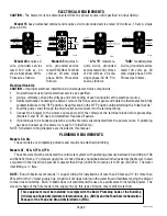
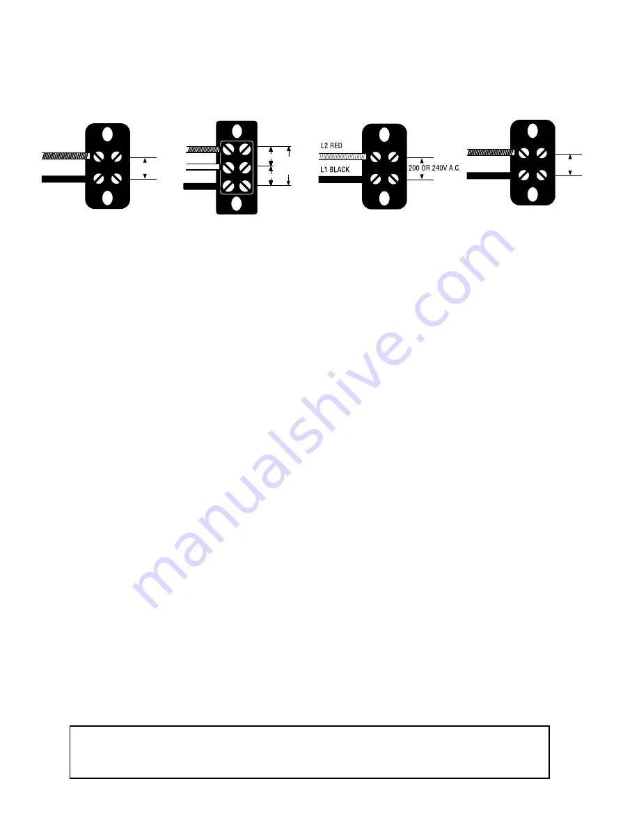
Model 15

 has an attached cordset and requires 2-wire grounded service rated 120 volts ac, 15 amp, single

phase, 60 Hz.

Model 35

 requires 3-

wire,  grounded  service
rated 120/208 or 120/240
volts  ac,  20  amp,  single
phase, 60 Hz.  Proceed as
follows:

Model 20

 requires 2-

wire,  grounded  service
rated  120  volts  ac,  20
amp, single phase, 60 Hz.
Proceed as follows:

Electrical Hook-Up
CAUTION –

Improper electrical installation will damage electronic components.

1.

An electrician must provide electrical service as specified.

2.

Using a voltmeter, check the voltage and color coding of each conductor at the electrical source.

3.

Before electrically connecting the brewer, remove the front and rear panel and rotate the thermostat knob fully
counterclockwise to the "OFF" position. Keep this knob in the "OFF" position until performing the "Initial Set-Up"

4.

Feed the power cord through the strain relief and connect it to the terminal block.

5.

Connect the brewer to the power source and verify the voltage at the terminal block before proceeding.
(Models S and ST-15 have cord attached. Replace all panels.

6.

If plumbing is to be hooked-up later be sure the brewer is disconnected from the power source.  If plumbing
has been hooked-up, the brewer is ready for "Initial Set-Up".

NOTE: Schematic wiring diagrams are included in this manual.

“A" & "B”

 models re-

quire  2-wire,  grounded
service rated 200 volts ac
or 240 volts ac, 20 amp,
single phase, 50 Hz. Pro-
ceed as follows:

"SDB”

 model requires

2-wire, grounded service
rated  100  volts  ac,  20
amp, single phase, 50 Hz.
Proceed as follows:

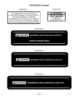
This equipment must be installed to comply with the Basic Plumbing Code of the Building
Officials and Code Administrators International, Inc. (BOCA) and the Food Service Sanitation
Manual of the Food and Drug Administration (FDA).

29251 011800

P1841

L2 RED

NEUTRAL

L1 BLACK

120V A.C.

120V A.C.

208 or

240V.A.C.

WHITE

NEUTRAL

L1 BLACK

120V.A.C.

WHITE

NEUTRAL

L1 BLACK

100V.A.C.

WHITE

P2185

P2185

P2193

Summary of Contents for S

Page 1: ...CE MANUAL BUNN O MATIC CORPORATION POST OFFICE BOX 3227 SPRINGFIELD ILLINOIS 62708 3227 PHONE 217 529 6601 FAX 217 529 6644 www bunnomatic com 29251 0000G 04 01 1998 Bunn O Matic Corporation S SA ST STA STF STFA BUNN ...

Page 2: ... employees of Bunn are not authorized to make modifications to this warranty or to make additional warranties that are binding on Bunn Accordingly statements by such individuals whether oral or written do not constitute warranties and should not be relied upon The Buyer shall give Bunn prompt notice of any claim to be made under this warranty by telephone at 217 529 6601 or by writing to Post Offi...

Page 3: ...Page 3 00656 0000 USER NOTICES Continued 00882 0000 02763 0000 02765 0000 02769 0000 29251 101598 ...

Page 4: ...follows Electrical Hook Up CAUTION Improper electrical installation will damage electronic components 1 An electrician must provide electrical service as specified 2 Using a voltmeter check the voltage and color coding of each conductor at the electrical source 3 Before electrically connecting the brewer remove the front and rear panel and rotate the thermostat knob fully counterclockwise to the O...

Page 5: ...funnel stops turn the thermostat knob to the ON position and wait approximately twenty minutes for the water in the tank to heat to the proper temperature Some water will drip from the funnel during this time this is due to expansion and should not occur thereafter 6 Empty the dispenser and initiate another brew cycle as directed 6A Models S SA Pour one pitcher of tap water into the screened area ...

Page 6: ... of grounds by gently shaking 3 Slide the funnel into the funnel rails 4 Place an empty dispenser beneath the funnel 5 Operate the brewer as directed 5A Models S SA Pour one pitcher of tap water into the screened area on top of the brewer 5B Models ST STF STA STFA Place the ON OFF switch in the ON upper position Momentarily press and release the start switch 6 When brewing is completed simply disc...

Page 7: ...lumbingfittingsaretightenedorloosened Thiswillhelp to avoid twists and kinks in the tubing Make certain that all plumbing connections are sealed and electrical connections tight and isolated This brewer is heated at all times Keep away from combustibles WARNING Exercise extreme caution when servicing electrical equipment Unplug the brewer when servicing except when electrical tests are specified F...

Page 8: ...rvice Start Switch for testing procedures See page 19 RefertoService Timerfortesting procedures See page 22 or 24 Refer to Service Solenoid Valve for testing procedures See page 18 A Direction of flow arrow must be pointing towards brewer B Remove the strainer flow con trol and check for obstructions Clear or replace Refer to Service Limit Thermo stat for testing procedures See page 16 Refer to Se...

Page 9: ...al water condi tions Excessive mineral build up onstainlesssteelsurfacescanini tiate corrosive reactions resulting in serious leaks 2 Control thermostat REMEDY Thebrewermustbelevelorslightly lower in front to syphon properly Inspect the tank assembly for ex cessive lime deposits Delime as required The water pressure to the brewer must be at least 20 psi 138 kPa A Early models Timer dial must indic...

Page 10: ...FA 1 Dispenser 2 Timer ST STF STA STFA REMEDY Thebrewermustbelevelorslightly lower in front to syphon properly Inspect the tank assembly for ex cessive lime deposits Delime as required Remove the solenoid valve and clear any obstructions Rebuild or replace the valve if necessary See page 18 RefertoService Timerfortesting procedures See page 22 or 24 Refer to Service Start Switch for testing proced...

Page 11: ... must be used for proper extraction A six hole stainless steel spray head must be used for proper extraction The BUNN paper filter must be centered in the funnel and the bed of ground leveled by gentle shak ing Placeanemptyfunnelonanempty dispenser beneath the sprayhead Initiate a brew cycle and check the water temperature immediately below the sprayhead with a ther mometer The reading should not ...

Page 12: ...nstall a regulator if necessary to lower the working pressure to ap proximately 50 psi 345 kPa Remove and clean lime off the tank heater See page 20 Check plumbing A Direction of arrow must be pointing towards brewer B Remove the strainer flow con trol and check for obstructions Clean or replace Refer to Service Solenoid Valve for testing procedures See page 18 RefertoService Liquidlevelcon trol b...

Page 13: ...wer from the power source before the removal of any panel or the replace ment of any component All components are accessible by the removal of thetopcoverortopwarmerhousingandfrontandrear inspection panels The top cover for Models with no top warmer and the top warmer housing is attached with four 8 32 screws Unplug upper wiring harness and set housing aside The front and rear inspection panels ar...

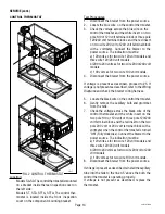
Page 14: ... the power source If voltage is present as described proceed to 5 If voltage is not present as described refer to the Wiring Diagrams and check the brewer wiring harness 5 Locate the black wire on the control thermostat 6 Gently remove the capillary bulb and grommet from the tank 7 Check the voltage across the black wire of the control thermostat and the white insert on the two pole 100 or 120 vol...

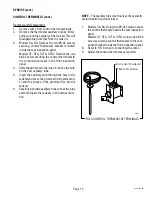
Page 15: ...the grommet to the line 4 5 above the bulb on the new capillary tube 5 Insert the capillary bulb through the hole in the tank lid and press the grommet firmly and evenly so that the groove in the grommet fits into the tank lid 6 Carefully bend the capillary tube so that the tube and bulb inside the tank are in the vertical posi tion NOTE The capillary tube must be clear of any electri cal terminat...

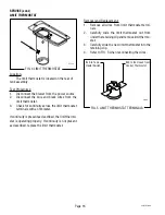
Page 16: ...ed the limit thermo stat is operating properly If continuity is not present as described replace the limit thermostat P1800 P1586 FIG 4 LIMIT THERMOSTAT FIG 5 LIMIT THERMOSTAT TERMINALS Removal and Replacement 1 Remove all wires from limit thermostat termi nals 2 Carefully slide the limit thermostat out from undertheretainingclipandremovelimitthermo stat 3 Carefully slide the new limit thermostat ...

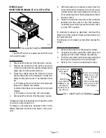
Page 17: ... the lower terminal the white red wire for the lower warmer switch the brown black wire for the top frontwarmerswitchortheblue blackwireforthe top rear switch 6 Check for continuity across the center and lower terminal with the switch in the ON position Continuity must not be present when the switch is in the OFF position If continuity is present as described reconnect the black wire to the center...

Page 18: ... Connect the brewer to the power source With ON OFF switch in the ON upper position press start switch and listen carefully in the vicinity of the solenoid valve for a clicking sound as the coil magnet attracts 7 Disconnect the brewer from the power source If the sound is heard as described and water will not pass through the solenoid valve there may be a blockage in the water line before the sole...

Page 19: ...erminals in the upper position If continuity is present as described reconnect the WHI YEL wire to the top terminal and the WHI ORA wire to the bottom terminal If continuity is not present as described replace the switch P1591 P1589 FIG 10 START SWITCH WHI YEL to Brew Timer TL3 WHI ORAto Brew Timer TL5 Removal and Replacement 1 Remove the WHI YEL and WHI ORA wires from the start switch 2 Compress ...

Page 20: ...iusly described 2 Disconnect the water supply tube from the sole noid 3 On brewers with faucet disconnect the faucet 4 Remove sprayhead and the hex nut securing the sprayhead tube to the hood Set aside for reas sembly 5 Disconnect the wire from the tank level probe 6 Remove the thermostat capillary bulb as de scribed in section for control thermostat 7 Disconnect the wires from the limit thermosta...

Page 21: ...ring the tank heater to the bottom of tank Remove tank heater with gaskets and discard 16 Install new tank heater with gaskets to the tank and secure with two hex nuts 17 Installtankwithlimitthermostat sprayheadtube and tank heater 18 Reconnect the inlet and outlet water lines to the solenoid and faucet 19 Secure spayhead tube to hood using a hex nut 20 Install sprayhead P1593 FIG 13 TANK HEATER T...

Page 22: ...hite yellow wire from terminal TL5 Checkforcontinuityacrossthetwowireswhenthe start switch is pressed to the START position If continuity is present as described reconnect the wires and proceed to 6 If continuity is not present as described refer to the Wiring Diagrams and check the brewer wiring har ness 6 With a voltmeter check the voltage across termi nals TL1 and TL4 when the ON OFF switch is ...

Page 23: ...t timer kit on the back side of the front access panel 6 Adjust the timer as required Refer to Late Model Timer section on the following pages MINUTES BUNN O M ATIC P N 2620 120 VAC P1595 FIG 15 BREW TIMER TERMINALS WHI RED TL1 to ON OFF Switch WHI TL2 to Terminal Block and Warmer Element 120V Two Pole 120 208V or 120 240V Three Pole Terminal Block RED TL2 to Terminal Block and Warmer Element 200V...

Page 24: ...ibed proceed to 5 If voltage is not as described disconnect the brewer from the power source and replace the timer 5 With a voltmeter check the voltage across termi nals TL1 and TL4 when the ON OFF switch is in the ON position Connectthebrewertothepower source and press the start switch The indication must be a 120 volts ac for two wire 120 volt models three wire 120 208 volt models and three wire...

Page 25: ...chieved 2 Setting brew volumes To set a brew volume first checkthattheSET LOCKswitchisinthe SET position on the circuit board Place the ON OFF switch in the ON position press and hold the START switch until three distinct clicks are heard and then release the switch Failure to release the switch within two sec onds after the third click causes the volume setting to be aborted and previous volume s...

Page 26: ... must again be a 120 volts ac for three wire 120 208 volt models and three wire 120 240 volt models after a delay of approximately 5 seconds b 200 to 240 volts ac for two wire 200 or 240volt models after a delay of approximately 5 seonds 10 Disconnect the brewer from the power source and remove the jumper wire from terminal 4 Location The liquid level probe is located within the tank lid inside th...

Page 27: ...models after a delay of approximately 5 seconds b 200 to 240 volts ac for two wire 200 or 240 volt models after a delay of approximately 5 seconds 15 Move the probe s flat end to the brewer housing The indication must be 0 16 Move the probe s flat end away from the brewer housing The indication should again be a 120 volts ac for three wire 120 208 volt models and three wire 120 240 volt models b 2...

Page 28: ...elay relayisoperating properly If continuity is not present as described replace the relay Removal and Replacement 1 Remove all wires from the relay terminals 2 Removethetwo 6 32screwssecuringtherelay and shield to the mounting bracket 3 With the two 6 32 screws secure the new relay and shield to the mounting bracket 4 Refer to FIG 21 when reconnecting the relay wires 5 Fold the flap of the protec...

Page 29: ...mbly from the brewer 3 Disconnect the two wires from the warmer ele ment terminals 4 Removethetwo 8 32nutssecuringthewarmer element to the warmer plate 5 Securely install new warmer element 6 Reconnect the two wires to warmer element terminals 7 Securelyinstallwarmerassemblyonthebrewer 8 Refer to FIG 23 when reconnecting the wires P1601 P1602 FIG 22 WARMER ELEMENTS FIG 23 WARMER ELEMENT TERMINALS ...

Page 30: ...ng an ohmmeter If continuity is present the thermal cutoff is operating properly If continuity is not present as described replace the thermal fuse Removal and Replacement 1 Disconnect the thermal cutoff from the tank heater terminal and the limit thermostat or wir ing harness 2 Remove thermal cutoff and discard 3 Connect new thermal cutoff to the tank heater terminal and the limit thermostat or w...

Page 31: ...Page 31 29251 052500 ...

Page 32: ...Page 32 29251 052500 ...

Page 33: ...Page 33 29251 052500 ...

Page 34: ...Page 34 29251 052500 ...

Page 35: ...Page 35 29251 052500 ...

Page 36: ...Page 36 29251 052500 ...

Page 37: ...Page 37 29251 052500 ...

Page 38: ...Page 38 29251 052500 ...

Page 39: ...Page 39 29251 052500 ...

Page 40: ...Page 40 29251 052500 ...

Page 41: ...Page 41 29251 052500 ...

Page 42: ...Page 42 29251 080400 ...

Page 43: ...Page 43 29251 052500 ...

Page 44: ......

Reviews: