17
WBR-G54 User Manual
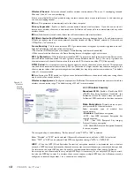
MRU (Maximum Receive Unit) Size
- Maximum Receive Unit (578-1492) when using PPPoE.
Keep Alive
- Enables the PPPoE client to send a Link Control Protocol (LCP) echo request to the PPPoE server
once per minute. If there is no reply within six minutes, the client disconnects. Set to
Disable
if frequent discon-
nection occurs.
Activation
- Enable/disable registered connection settings. If disabled, the connection is not permitted.
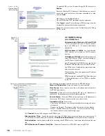
4.2.2 Network WAN
WAN side (Internet) parameters.
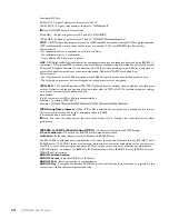
Host Name
- Enter the host name as desired.
Default Gateway
- A default gateway IP should
be assigned to the AirStation. If unknown, leave
blank. If
Auto IP as sign ment from DHCP
Server
is selected in section 4.2.1, a gateway IP is
assigned automatically, provided the DHCP server
is set to provide one.
DNS Server Address
- Enter the primary and
secondary DNS address(es) of the server to be
used by the AirStation for DNS resolution.
If DNS was set to
Do not use (Section 4.1.4
), leave blank. If
Auto IP as sign ment from DHCP Server
was selected, DNS addresses are assigned automatically, provided the DHCP server is set to provide them.
Port Number for WEB Settings
- Set a speci
fi
c port number when remote setup of the AirStation is
planned.
PING from WAN
- Allows a PING test from WAN side. Select
Do not respond
or
Respond
.
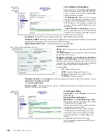
4.3 Network Setting
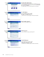
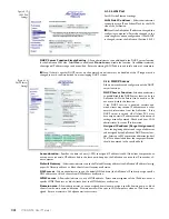
4.3.1 Routing Setup
RIP transmission to WAN
- Allows RIP trans-
mission or None (no RIP) to WAN
RIP reception from WAN
- Allows RIP recep-
tion or None (no RIP) from WAN
RIP transmission to LAN
- Allows RIP transmis-
sion or None (no RIP) to LAN
RIP reception from LAN
- Allows RIP reception
or None (no RIP) from LAN
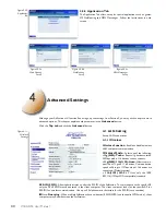
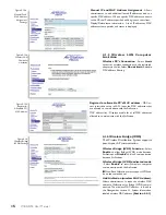
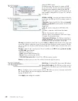
Click
Add Route
to Add Routing Table Entry
•
Destination address
- Network IP address and subnet
mask.
•
Gateway
- Address through which the packet passes before
it reaches the des ti na tion address.
•
Metric
- Number of routers (1-15) to be passed before the
packet reaches its destination.
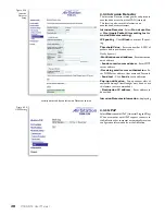
Display current information
- Allows administrator to
view and delete routing information.
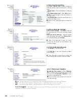
Network of
WAN
Fig ure 4.3.1
Routing Setup
Fig ure 4.3.1b
Add routing
table entry

