SimpliMet™ 3000 Drawings
31
MA201435_13.1
[Original Instructions]
6/25/2012
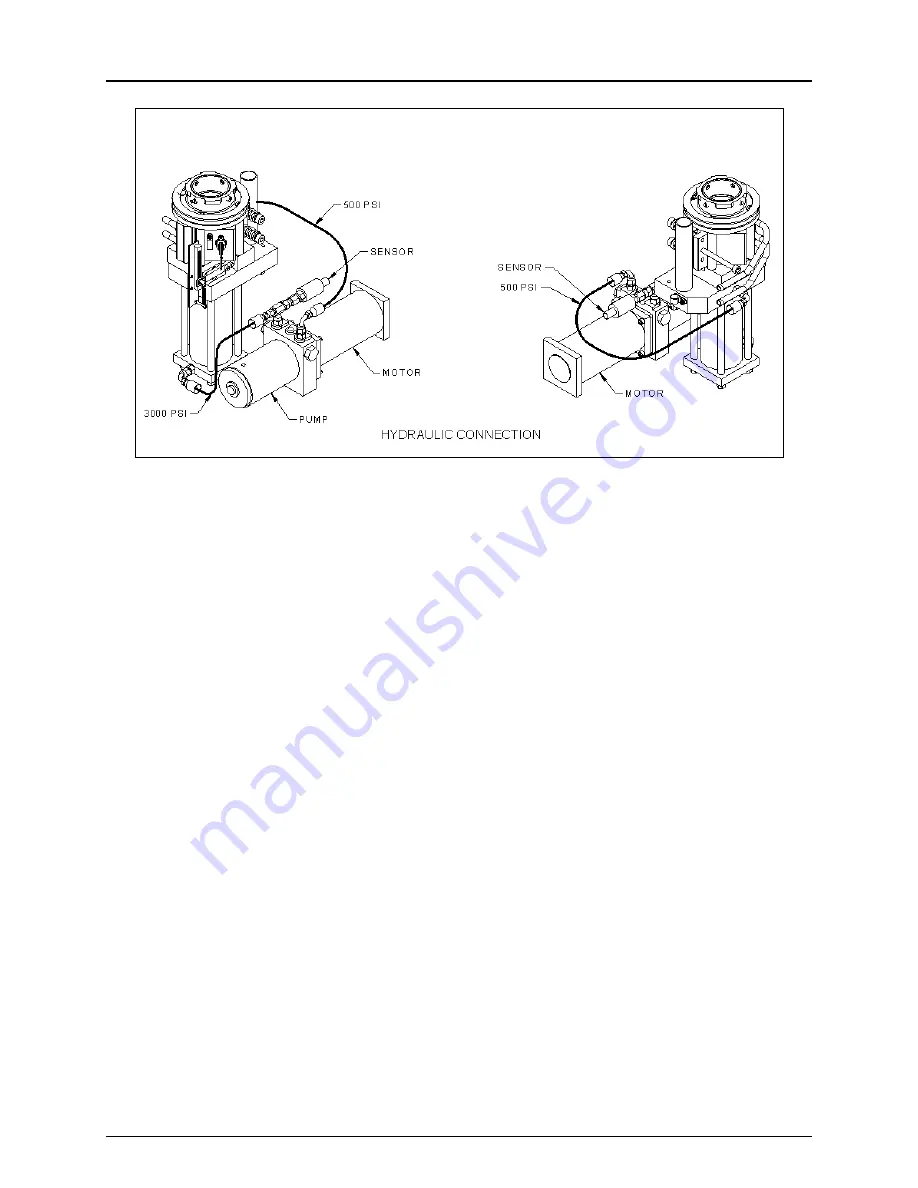
Figure 21 SimpliMet 3000 Hydraulic Connections Diagram
Page 1: ...MA201435_13 1 6 25 2012 www buehler com SimpliMet 3000 Automatic Mounting Press ...
Page 2: ...een a leading manufacturer of scientific instruments and supplies for use in materials analysis Buehler products are used throughout the world in manufacturing facilities quality laboratories and universities to analyze all types materials including Ferrous and Non ferrous metals Thermal spray coatings Printed Circuit Boards Fasteners Ceramics Composites Semiconductors Rocks Glasses Plastics Compa...
Page 3: ...95 EN 55082 1 1995 EN 61000 4 4 EN 61000 4 5 EN 61000 6 2 EN 50140 Quality Management System ISO 9001 2008 Registered firm Underwriters Laboratories Inc QMS Cert 10001679 1130 W Lake Cook Road Suite 340 Buffalo Grove IL 60089 USA This machine is CE marked Lake Bluff Illinois USA Prepared by Kate Watling Technical Communicator THIS MANUAL IS A CUSTOM GENERATED DOCUMENT IT INCLUDES ALL REVISIONS REL...
Page 4: ...ol Panel 13 Parameters Fields 14 L1 Screen 16 L2 Screen 17 Method Screen 18 Making a Mold 19 Setting Parameters 19 Saving a Method 19 Loading a Method 20 Preparing the RAM 20 Starting a Cycle 20 Additional Features 21 Mold Cylinder Pre Warming 21 Mold Closure Sensor 21 HEATING and COOLING 21 Auto RAM Up Down 21 Maintenance 22 Monthly 22 Periodically 22 SimpliMet 3000 Diagnostic Screen 23 Trouble S...
Page 5: ...rized repair This warranty covers all Buehler costs associated with the replacement of defective materials e g parts and labor If for any reason this unit must be returned to Buehler for warranty service please contact Buehler Service at www Buehler com or 1 800 283 4537 for prior authorization and shipping instructions If outside the USA or Canada contact your local Buehler Representative Please ...
Page 6: ...achine in explosive atmospheres such as in the presence of flammable liquids gases or dust Sparks may ignite the dust or fumes Maintain the SimpliMet 3000 care Properly maintained machines are less likely to bind and are easier to control Any alteration or modification is a misuse and may result in a dangerous situation Only qualified repair personnel must perform machine service Service or mainte...
Page 7: ...discrepancy Carefully unpack and check that the following items have been received Accessory Kit 206 Scrapper Tool Scoop Sample EpoMet Molding Compound Sample PhenoCure Resin Powder Sample Release Agent DANGER indicates a hazardous situation which if not avoided will result in death or serious injury WARNING indicates a hazardous situation which if not avoided could result in death or serious inju...
Page 8: ...bs 33 kg and two persons are required to safely lift the unit from the shipping carton Follow local safety practices to lift the SimpliMet 3000 unit from the shipping carton Improper lifting can result in machine damage Personal Injury Improper lifting of the SimpliMet 3000 can result in personal injury The SimpliMet 3000 is bolted to a wood base for protection during shipping Open areas are provi...
Page 9: ...ource Use of the Buehler 49 2105 Water Filtration Kit is highly recommended The recommended cooling water flow rate is a minimum of 0 5 gallons min 2 liters min with a water pressure between 45 75 psi 3 5 bar The maximum working pressure is 125 psi 8 6 bar Water supply parameters that are different will not affect the operation of the SimpliMet 3000 but different coolant times may be needed Coolin...
Page 10: ...rain hose with clamp if necessary NOTICE Do not leave the drain hose exposed A short burst of steam will exit the drain hose at the beginning of a cooling cycle The main water supply must be shut off at night or when the machine is left unattended If for any reason the SimpliMet 3000 has to be moved close the vent valve before moving and open before operating Drain Hose Water Hose Vent Valve ...
Page 11: ...sk of electrical shock This plug will fit in a polarized outlet only one way Disconnect the power supply before making any electrical adjustments Capacitors inside the machine may retain a charge even if the machine is disconnected from the power supply The Specification Plate is located on the back of the SimpliMet 3000 Check that Specification Plate values for voltage current and power consumpti...
Page 12: ...sure will be warm to the touch 1 Connect the SimpliMet 3000 to an electrical supply 2 Move the power switch to the ON position The front panel will light up 3 Install the Upper Ram and insulation parts see Figure 2 Insert the Spindle Assembly knob and threaded rod through the top of the press Place a spacer insulator disc on the Spindle Assembly Screw Upper Ram to the Spindle Assembly The Upper Ra...
Page 13: ...der Clamp Screw 5 Remove the shipping tube 6 Insert the Mold Cylinder Insulator Ring into the Mold Closure Align the holes of the Insulator Ring with the screws see Figure 5 Figure 5 Mold Cylinder Insulator Ring 7 Insert the Mold Assembly until it sits level with the top of the Mold Closure see Figure 6 Figure 6 Mold Assembly in the Mold Closure 8 Install the eight setscrews P N R10496 Do not tigh...
Page 14: ...ay down the Mold Cylinder to aid in centering the mold 11 Place and hold the Upper Ram inside the Mold This will help in centering the mold see Figure 8 Figure 8 Upper Ram on the Ram Assembly 12 Using the supplied wrench turn the Mold Cylinder Clamp Screw counter clockwise until loose The Mold Assembly will be secured in the Mold Cylinder Figure 9 Mold Cylinder Clamp Screw ...
Page 15: ...gure 10 details an off centered Ram Assembly caused by over tightening of the setscrews Figure 10 Off centered Ram Assembly 16 Raise and lower the Ram Assembly to verify smooth operation Before making a mold check that the Upper Ram easily locks and disengages from the Mold Cylinder Lower the Upper Ram into the Mold Cylinder and turn the bayonet cap handles clockwise to lock the Upper Ram into the...
Page 16: ...ld cylinder use the MANUAL COOL function This will lower the mold cylinder to a safe handling temperature Clean the molding powder flash from the upper and lower RAM after completing each molding cycle Apply Release Agent after every fifth or sixth mold to prevent build up of molding powder on the inside of the mold cylinder and the outside faces of the upper and lower RAM ...
Page 17: ...p and display the default parameters Figure 11 SimpliMet 3000 Front Control Panel ON Power On The Power On button will activate the SimpliMet 3000 OFF Power Off The Power Off button will deactivate the SimpliMet 3000 Increase The Increase button will incrementally increase raise a parameter s value Decrease The Decrease button will incrementally decrease lower a parameter s value Parameter Scroll ...
Page 18: ...re applied to the specimen Use the Increase or Decrease buttons to select between 1200 psi to 4400 psi 80 bar 300 bar in 100 psi 5 bar increments TEMP ERATURE 300F PRELOAD PRESSURE OFF MOLD SIZE 1 25IN Figure 13 Parameter Fields 2 TEMPERATURE Displays the temperature selected Use the Increase or Decrease buttons to select a temperature variable between 120 F 50 C and 360 F 180 C in 20 F 10 C incre...
Page 19: ...GE Displays the language Use the Increase or Decrease buttons to select a different language of choice English Chinese French Korean German Japanese Portuguese METHOD LOADED Displays the selected method applied to a cycle Use the Increase or Decrease buttons to select between four pre programmed Buehler methods or 25 user defined methods If no method is desired select NONE Four Buehler Pre Program...
Page 20: ... the CYCLE START button is pressed in the middle of a cycle the cycle will stop RAM MOVE Press the RAM MOVE button to activate the movement of the RAM MANUAL COOL Press the MANUAL COOL button to active cooling when not in a cycle THERMOPLASTIC Press the THERMOPLASTIC button to activate the thermoplastic mode Note Thermoplastic molds require a special heating and cooling cycle to prevent cloudiness...
Page 21: ...AD METHOD Opens a screen to scroll through four pre programmed Buehler Methods per mold size and 25 user defined methods to operate the press Four pre programmed Buehler Methods PHENOLIC EPOMET TRANSOPTIC DIALLYL PH Note These methods parameter values can be changed and saved as user defined methods Method 1 Method 25 to better suit individual needs Level 2 Press the L2 button to scroll to the L1 ...
Page 22: ...to the L2 Screen without saving the selected method SAVE Loads and saves the parameters of the selected method and exits to the L2 Screen NEXT Scrolls to one of the four pre programmed Buehler Methods per mold size or to the next displayed number of a user defined method PREV Returns to one of the four pre programmed Buehler Methods or the previous displayed number of the user defined method ...
Page 23: ...parameter field Use the Increase or Decrease buttons to select a TEMPERATURE 120 F to 360 F 5 Use the Parameter Scroll button to scroll to the PRELOAD parameter field Use the Increase or Decrease buttons to select a PRELOAD 0 400 psi 6 Using the Parameter Scroll button scroll to the MOLD SIZE parameter field The mold sensor will automatically display the MOLD SIZE Saving a Method Once all the para...
Page 24: ...ing cycle is complete a Once the SimpliMet 3000 is pressurized the screen will change to display PRE HEATING During the PRE HEATING phase the temperature is increasing to reach the selected temperature 120 F to 360 F b Once the selected temperature is reached the HEAT TIME parameter field will begin to count down The temperature will remain at the set temperature for the duration of the HEAT TIME ...
Page 25: ... when CYLINDER OPEN appears on the LCD screen HEATING and COOLING The LCD screen will display HEATING or COOLING in the lower right hand corner indicating the section of an automatic cycle The time remaining in either a heating or cooling cycle is also displayed Auto RAM Up Down Once a cycle is complete press the RAM MOVE button until AUTO RAM UP is displayed on the LCD Screen The RAM will continu...
Page 26: ...ws for tightness Check that the screws are not pushing the cylinder out of vertical alignment Check that the mold cylinder clamp screw is completely turned counter clockwise against the stop Swab the working surfaces of the mold assembly with Release Agent to maintain smooth operation Check the RAM and cylinders for damage and any hard resin Remove any resin with a soft scraper or by swabbing with...
Page 27: ...X VAC CYCLE HOURS TOTAL HOURS MAX VAC MOLD SENSE ON Figure 18 SimpliMet 3000 Diagnostic Screen CYCLE HOURS Displays the amount of time accumulated between Cycle Start and Cycle Stop TOTAL CYCLES Displays the amount of cycles accumulated when the CYCLE START button is pressed MAX VAC Displays the largest amount of voltage exposed to the unit 3 Press the button to change to the L1 screen MOLD SENSE ...
Page 28: ...ticks when lowered Build up of molding material flash around lower ram Eject ram and clean the flash off the lower ram Not able to close the mold closure Build up of molding material flash around upper ram Clean the flash from upper ram and from the top of the cylinder Hot mold after a full cycle No cooling water 0 zero minutes of cooling time Connect the unit to a water supply Change cooling time...
Page 29: ... Cool Heat Cool Heat Cool Heat Cool Phenolic 150 C 300 F 290 bar 4200 psi 1 0 3 0 1 0 3 0 1 0 3 0 2 0 3 0 Diallyl Phthalate 150 C 300 F 290 bar 4200 psi 1 0 3 0 1 0 3 0 1 0 3 0 2 0 3 0 EpoMet 150 C 300 F 290 bar 4200 psi 1 0 3 0 1 0 3 0 1 0 3 0 2 0 3 0 KonductoMet 150 C 300 F 290 bar 4200 psi 1 0 3 0 1 0 3 0 1 5 3 0 2 0 3 5 ProbeMet 150 C 300 F 290 bar 4200 psi 1 0 3 0 1 0 3 0 1 5 3 0 2 0 3 5 Tran...
Page 30: ... heat time Insufficient molding pressure Increase molding pressure Bulging or soft mount Insufficient cure Increase heat time Increase molding pressure Radial cracks or splits Sample section to large Increase mold size Sample corners too sharp Decrease sample size Round sample edges Circumferential Cracks Absorbed moisture Store resin in a dry area Keep resin containers closed Dry resins at low te...
Page 31: ...rocesses our materials and our people in order to reduce the environmental impacts associated with our products To help conserve natural resources and to protect human health and environment please follow your state and local regulations on recycling and disposing of waste consumables or parts related to your Buehler machine For End Of Life on Buehler machines if recycling and disposal facilities ...
Page 32: ...d assembly with duplex spacer 1 1 2 Diameter 20 2403 Mold assembly with duplex spacer 2 Diameter 20 2404 Mold assembly with duplex spacer 25 mm Diameter 20 2405 Mold assembly with duplex spacer 30 mm Diameter 20 2406 Mold assembly with duplex spacer 40 mm Diameter 20 2407 Mold assembly with duplex spacer 50 mm Diameter 20 2408 Cleaning Brush 1430S097 Scrapper Tool 1330S49 Water Filter 49 2105 4 mm...
Page 33: ...SimpliMet 3000 Drawings 29 MA201435_13 1 Original Instructions 6 25 2012 Figure 19 SimpliMet 3000 Upper Assembly Diagram 1435900B ...
Page 34: ...SimpliMet 3000 Drawings 30 MA201435_13 1 Original Instructions 6 25 2012 Figure 20 SimpliMet 3000 Lower Assembly Diagram 1435900C ...
Page 35: ...SimpliMet 3000 Drawings 31 MA201435_13 1 Original Instructions 6 25 2012 Figure 21 SimpliMet 3000 Hydraulic Connections Diagram ...
Page 36: ...SimpliMet 3000 Drawings 32 MA201435_13 1 Original Instructions 6 25 2012 Figure 22 SimpliMet 3000 Wiring Diagram 1435900E ...
Page 37: ...SimpliMet 3000 Drawings 33 MA201435_13 1 Original Instructions 6 25 2012 Figure 23 SimpliMet 3000 Packaging Diagram 1435900D ...
Page 38: ...L 1 EA 203100 BLACK PHENOLIC POWDER BULK 1 LB 203380004 EPOMET MOLDING COMPOUND SAMPLE 1 EA L203380064S LABEL FOR EPOMET MLDG SAMPLE 1 EA R6169 4 OZ POLYPROPYLENE JAR 1 EA R6170 CAPS FOR 4 OZ JAR 1 EA 203380A EPOMET MOLDING COMPOUND BULK 0 25 LB 208185002 RELEASE AGENT 2 OZ 1 EA C1800234 WASHER 5 16IN I D X 1 25 4 EA IS492105 INSTRUCTIONS H2O FILTRATION 1 EA R10269 POLY SHEET 48 X 72 2 MIL 1 EA R1...
Page 39: ...SS 2 EA C191032 SCREW M4 X 8 PN HD 5 EA R0371 REDUCING BUSHING 1 8IN X 1 4IN 1 EA R0535A TERMINAL 6 BLK SPADE 22 16 FI 1 EA R0609LWE WASHER EXT 8 STN STL 2 EA R0615W WASHER 1 4IN SS 4 EA R0621LW LOCK WASHER 3 8IN SS 2 EA R10067 PRESS XDUCER HYDRLC 3000 PSI 1 EA R10070 ADAPTER BSP 1 8 7 16 2 EA R10071 ADAPTER 7 16 7 16 SAE O RING 2 EA R10073 ADAPTER 7 16 7 16 3 WAYS 1 EA R10077 END MALE PIPE ELBOW ...
Page 40: ...ODX1 4 ID 50 DURO 4 EA R8773 FIT 10 32 1 4 INST ADPTR 1 EA R8774 FIT 1 8 NPT 1 4 INST ADPTR 1 EA R8882 ELBOW 1 8 NPT 3 8 TUBE 1 EA R8992 INLET POWER IEC SNAP IN 1 EA R8993 BREAKER CIRCUIT 15 AMP 2 POLE 1 EA R9026 UNION REDUCING 375 250 TUBE 2 EA R9031 WASHER 1 4 X 50 X 03 SS EXT 1 EA R9095 CONNECTOR 187 MALE TAB BRASS 1 EA R9422 SCREW 10 32 X 3 8 PH PAN ST SS 4 EA R9639 SCREW 10 32 X 1 2 SOC FL HD...
Page 41: ...007 KIT SIMPLIMET 1000 3000 PARTS 1 EA CPK1441 SLEEVE 1 EA C2041052 CLIP WORM DRIVE SIZE 16 1 EA R6875 CARTON 26 1 2X20 7 8X22 5 8DW 1 EA R6887 INSERT FOR SIMPLIMET 1 EA 1430S011 RING BAYONET SIMPLIMET 1 EA 1430S012 SPACERS SIMPLIMET 4 EA 1430S015 SPACER HEAT RESISTANT 1 EA 1430S016 CAP BAYONET 1 EA 1430S017 TOP HOUSING 1 EA 1430S021 RETAINER CAP 1 EA 1430S026 TOP RAM SPINDLE 1 EA 1430S027MOD CYLI...
Page 42: ... 1430S155 SCREW ADJUSTING 1 EA 1430S156 PLATE ABUTMENT 1 EA 1430S157 SPRING COMPRESSION 2 EA 1430S158 BOLT SHOULDER 2 EA 1430S167 FITTING WATER TUBE 2 EA 1435S011 HYDRAULIC CYLINDER SIMP 1K 3K 1 EA 1435S502 CABLE MOLD SENSOR 1 EA 1435S504 NAMEPLATE SIMPLIMET 3000 NEW 1 EA 1435S505 PCB LOGIC LCD CONTROL LF 3K 1 EA 1435S507 PCB MOLD SENSOR SIMP 3K LF 1 EA 1790S062 PLATE BILINGUAL CAUTION 1 EA 203000...
Page 43: ...SimpliMet 3000 Method Log 39 MA201435_13 1 Original Instructions 6 25 2012 METHOD NUMBER HEAT TIME COOL TIME PRESSURE TEMPERATURE MATERIAL MOLD SIZE ...
Page 44: ...er ca Email info buehler ca Buehler Canada Service 10 Carlow Court 2 Whitby Ontario L1N 9T7 Tel 800 268 3593 905 201 4686 Fax 905 201 4683 Email info buehler ca Buehler UK Service 101 Lockhurst Lane Coventry CV6 5SF England Tel 44 0800 707 6273 Fax 44 0800 707 6724 Buehler United Kingdom Website www buehler co uk E mail sales buehler co uk Service E mail service buehler co uk Buehler France Tel 33...
Page 45: ...Notes 41 MA201435_13 1 Original Instructions 6 25 2012 ...