


Technical sheets - Automation
MY HOME
7
1 2
3 4
6
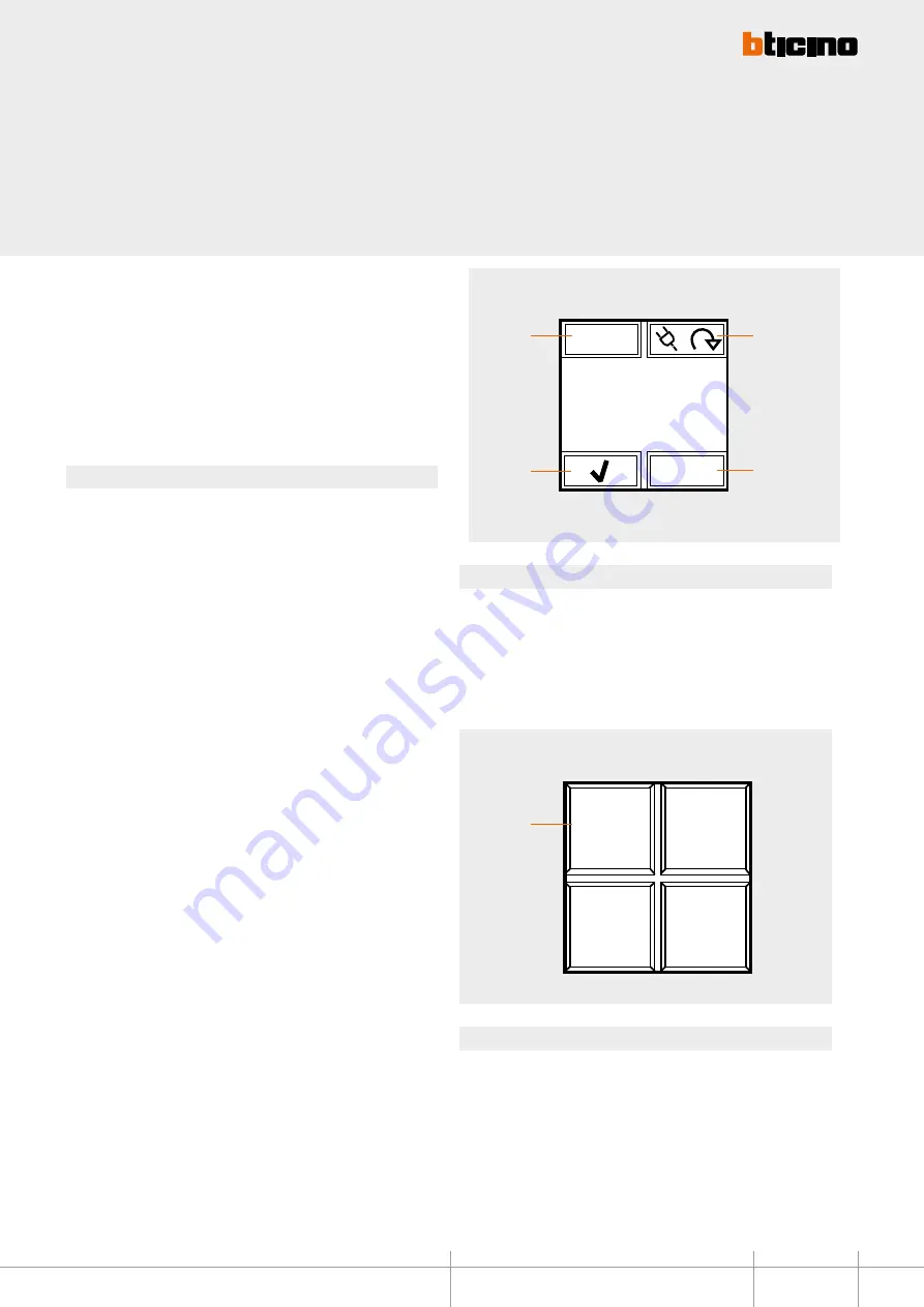
Oven
ON
i
1
1
2
3
4
- LOAD MANAGEMENT mode
This mode, only available if Local Display is configured using the software, gives the
possibility of displaying loads, with their priority levels, and force their activation. The
device can manage up to 20 loads; if these are connected to actuators with current
sensor it will be possible to display other load information, like the instantaneous power
consumption.
When the central unit for load management intervenes on a load, the device (if enabled
during the configuration) notifies the event with an indication on the display and an
audible notification.
Functions
After the configuration of the device it will be possible to select the various loads using
icon 1.
Icon 4 is disabled until the moment the central unit disables the load; when this
happens, the icon becomes active, and can be selected to force the activation of the load.
In this condition, icon 3, used to intervene on the status of the load, is disabled.
However, if icon 4 is disabled, it will be possible to select icon 3 to pre-force the load,
and avoid disconnection in case of intervention of the central unit when consumptions
are exceeded.
If the loads are connected to actuators with current sensor, use icon 2 to access a
submenu that can be used to display the instantaneous power consumption, as well as
information form the line total consumption meters. While in this submenu, you can use
the RESET icon to reset the meters. Press key 2 for 3 seconds to access the menu used for
setting the time, the date, and the sound notification (beep).
Legend
1. selection of the load to control
2. display of consumption data and device setup
3. activation/deactivation of the load
4. forced activation of the load disconnected by the energy management central unit,
due to consumptions being exceeded.
- Advanced CEN SCENARIO mode
For systems with MH200N scenario programmers, Local Display can be used to enable 1
of the 4 scenarios displayed. This is done using the associated icons.
This function is only available if Local Display has been configured using the software.
Legend
1. scenario indication icon
BT00517-a-UK
HD4891 - HC4891 - HS4891
L4891 - N4891 - NT4891


