background image

4/10

CONTENTS

Technical data sheet:  S000092412EN-1 

Updated: 

Created: 02/06/2016

Cat No(s): LN4691KNX - H4691KNX

KNX temperature control panel

  9. SETTINgS

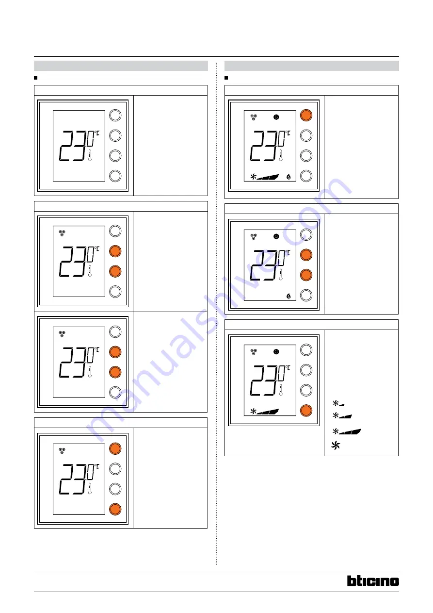
9.1  Display during installation

No configuration

MODE

FAN

+

-

MODE

FAN

+

-

MODE

FAN

+

-

MODE

FAN

+

-

MODE

FAN

+

-

MODE

FAN

+

-

MODE

FAN

+

-

MODE

FAN

+

-

A

The temperature flashes 

slowly to indicate that the 

control panel has not been 

configured.

Temperature calibration

MODE

FAN

+

-

MODE

FAN

+

-

MODE

FAN

+

-

MODE

FAN

+

-

MODE

FAN

+

-

MODE

FAN

+

-

MODE

FAN

+

-

MODE

FAN

+

-

A

After the product switches 

ON, wait at least 30 minutes 

before starting temperature 

calibration.
Press + and - at the same 

time (> 7 seconds); the 

thermometer icon starts 

flashing quickly. Release 

the keys.

MODE

FAN

+

-

MODE

FAN

+

-

MODE

FAN

+

-

MODE

FAN

+

-

MODE

FAN

+

-

MODE

FAN

+

-

MODE

FAN

+

-

MODE

FAN

+

-

A

After releasing the keys, you 

can increase or decrease the 

temperature detected using 

+ and – . Wait a few seconds, 

or press MODE or FAN to 

terminate the procedure.

Programming

MODE

FAN

+

-

MODE

FAN

+

-

MODE

FAN

+

-

MODE

FAN

+

-

MODE

FAN

+

-

MODE

FAN

+

-

MODE

FAN

+

-

MODE

FAN

+

-

A

Press MODE and FAN at the 

same time (> 7 seconds). 

The control panel displays 

Pr (Programming mode). 

Without further action, 

the display will revert to 

its initial status after 30 

minutes.
Programming can also be 

performed by pressing the 

Prog and Reset button on 

the back of the display.

   9.  SETTINgS (continued)

9.2  Display during use

ambient temperature and/or setpoint

MODE

FAN

+

-

MODE

FAN

+

-

MODE

FAN

+

-

MODE

FAN

+

-

MODE

FAN

+

-

MODE

FAN

+

-

MODE

FAN

+

-

MODE

FAN

+

-

A

With ETS, you can choose 

to display the setpoint 

(the thermometer icon 

is not shown) and/or the 

ambient temperature 

(the thermometer icon is 

shown). The temperature 

unit of measurement is °C or 

°F and can be chosen via a 

communication object.
A short press on the MODE 

button, toggles between 

Comfort mode and 

Protection mode.

local setpoint modification

MODE

FAN

+

-

MODE

FAN

+

-

MODE

FAN

+

-

MODE

FAN

+

-

MODE

FAN

+

-

MODE

FAN

+

-

MODE

FAN

+

-

MODE

FAN

+

-

A

Press + or - to change the 

local setpoint. The new 

temperature flashes. 
After 5 seconds without 

action, the display stops 

flashing and the new value 

is accepted as the new 

temperature setpoint. 

The local setpoint can only 

be modified in Comfort 

mode.

Fan coil speed

MODE

FAN

+

-

MODE

FAN

+

-

MODE

FAN

+

-

MODE

FAN

+

-

MODE

FAN

+

-

MODE

FAN

+

-

MODE

FAN

+

-

MODE

FAN

+

-

A

If the thermostat is 

configured for management 

of a fan coil type load, by 

pressing the FAN key you 

can scroll through the fan 

speeds available, selecting 

one of the following values.

Press FAN to set the fan 

speed to the desired level:

MODE

FAN

+

-

MODE

FAN

+

-

MODE

FAN

+

-

MODE

FAN

+

-

MODE

FAN

+

-

MODE

FAN

+

-

MODE

FAN

+

-

MODE

FAN

+

-

A

MODE

FAN

+

-

MODE

FAN

+

-

MODE

FAN

+

-

MODE

FAN

+

-

MODE

FAN

+

-

MODE

FAN

+

-

MODE

FAN

+

-

MODE

FAN

+

-

A

MODE

FAN

+

-

MODE

FAN

+

-

MODE

FAN

+

-

MODE

FAN

+

-

MODE

FAN

+

-

MODE

FAN

+

-

MODE

FAN

+

-

MODE

FAN

+

-

A

MODE

FAN

+

-

MODE

FAN

+

-

MODE

FAN

+

-

MODE

FAN

+

-

MODE

FAN

+

-

MODE

FAN

+

-

MODE

FAN

+

-

MODE

FAN

+

-

A

     Speed 1

Speed 2

Speed 3

 Automatic 

operation

Summary of Contents for H4691KNX

Page 1: ... 3 3 Mechanical characteristics 2 4 Dimensions 2 5 Connection 3 6 Installation 3 6 1 Physical installation 3 6 2 System installation 3 7 Operating modes 3 8 System applications 3 8 1 Heating application 3 8 2 Cooling application 3 8 3 Heating and Cooling application 3 9 Settings 4 9 1 Display during installation 4 9 2 Display during use 4 10 Standards and approvals 5 11 Maintenance 5 12 Communicat...

Page 2: ... associations must be made via ETS software ETS versions 3 4 and 5 only 2 Description 1 2 3 4 5 6 MODE FAN 7 8 9 13 12 11 10 14 15 1 Heating mode 2 Cooling mode 3 Comfort mode 4 Eco mode 5 Frost Overheat protection 6 MODE key A short press changes the device operating mode a long press changes the function 7 key increases the set value 8 key decreases the set value 9 FAN key sets the fan coil spee...

Page 3: ...ve Cooling application only cooling is active Cooling and Heating application 8 1 Heating application If the measured temperature is lower than the reference value the heating system is activated and the corresponding symbol appears on the display When the temperature is reached the control panel switches the zone off and the icon disappears Note The heating icon is always displayed 8 2 Cooling ap...

Page 4: ...tinued 9 2 Display during use Ambient temperature and or setpoint MODE FAN MODE FAN MODE FAN MODE FAN MODE FAN MODE FAN MODE FAN MODE FAN A With ETS you can choose to display the setpoint the thermometer icon is not shown and or the ambient temperature the thermometer icon is shown The temperature unit of measurement is C or F and can be chosen via a communication object A short press on the Mode ...

Page 5: ...X H4691KNX comply with Directive 2014 53 EU The full text of the EU declaration of conformity is available at the following internet address www bticino com 11 Maintenance Clean the surface with a cloth Do not use acetone tar removing cleaning agents or trichloroethylene Caution Always test before using other special cleaning products Note All technical information is available at NFC compatible A...

Page 6: ...21 C In the event of a power cut the value is saved and restored when the power returns 5 Heating Cooling Temperature setpoint limit high 9 001 2 Bytes CW Highest limit for the temperature setpoint received from the bus Default value 35 C In the event of a power cut the value is saved and restored when the power returns 6 Heating Cooling Temperature setpoint limit low 9 001 2 Bytes CW Lowest limit...

Page 7: ... open or Heating valve open received from the bus Default value 0 17 Heating Cooling Heating valve status 1 002 1 bit CW Heating valve open received from the bus Only in 4 tube installations 1 Heating valve open 0 Heating valve closed default value 18 Heating Cooling Cooling Heating Cooling valve status 1 002 1 bit CW In 4 tube installation Cooling valve open received from the bus In 2 tube instal...

Page 8: ...n speed off default value 27 Fan Fan Speed 2 status 1 002 1 bit CW Fan speed 2 received by the bus Only if 1 bit Fan function is active 1 Fan speed 2 0 Fan speed off default value 28 Fan Fan Speed 3 status 1 002 1 bit CW Fan speed 3 received by the bus Only if 1 bit Fan function is active 1 Fan speed 3 0 Fan speed off default value 29 Information Window status 1 002 1 bit CW Window status received...

Page 9: ...it will automatically switch the backlight to normal mode after a button is pressed it will revert to ECO after 30 s of inactivity 12 COMMUNICATION OBJECTS CONTINUED 12 2 ETS parameters continued Activate standby mode With this parameter you can decide whether or not to use the standby display mode monitor switch OFF If YES you will then be able to switch between normal and standby display mode by...

Page 10: ...for valve With this parameter you can choose the type of object 1 bit or 1 byte to communicate the status of the heating cooling valve s The choice must be the same as for the actuator 1 bit objects 15 16 are not active objects 17 18 are active 1 byte objects 17 18 are not active objects 15 16 are active Add Object HVAC mode If yes object 8 HVAC mode is active Add Object HVAC Status If yes object ...

Reviews: