Installation Instructions
18
User Manual CPM II2066en Rev.B
© BTG 2019
2.5.2.2
HCM-8010 Connections
NOTE!
The functions of the connections for each instrument type can be found in the
connection tables for HCM-8010 in section 5:
P1
P3
P2
P4
P6
P5
P7
P9
P8
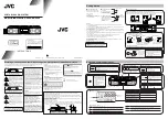
Fig 12 HART Communication
Module HCM-8010
P3
HCM-8010
P2
P1 P4
P5
P6
P7
P8
P9
Digital In 2
Digital In 1
Digital In 3
Digital Out
Analog In 4-20 mA
Active Analog Out 4-20 mA
Active Analog Out 2 (4-20 mA)
Active Analog Out 3 (4-20 mA)
Active Analog Out 4 (4-20 mA)
Active Analog Out 5 (4-20 mA)
Digital In 4
Digital Out 2
Solenoid Valve 4
Solenoid Valve 5
Transmitter
cable
Cable shield
SFM-8000
DI3
P1
DO
DI1
P2
DI2
AO1
P3
AI1
AO2
P4
AO3
AO4
P5
AO5
AI
P6
23
4
DI4
P7
DO2
SV4
P8
SV5
SV
P9
12
3
+
-
LOAD
+24 V
+24 V
+24 V
+24 V
+24 V
Analog In 2 (4-20 mA)
Analog In 3 (4-20 mA)
Analog In 4 (4-20 mA)
24 V
+24 V
Solenoid Valve 1
24 V
Solenoid Valve 2
Solenoid Valve 3
+
-
LOAD
+24 V
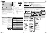
Fig 13 Connection of
HCM-8010 cables
CAUTION
Always connect
the cable shield!
CAUTION!
The cable shield must always
be connected to the upper
connection point on the shield
filter module, and kept
separated from the transmitter
cable shield.
NOTE!
For HCM-8010, only active
analog output is available.


