5
Assembly and commissioning/start-up
22/38
iPQ-Spectral – Spectral measuring head (C11 SensorUnit)
5
Assembly and commissioning/start-up
This chapter describes assembly and commissioning/start-up of
the spectral measuring head and the motor traverse bar. For de-
tailed information about the mechanical and/or electrical installa-
tion work, please refer to the installation manual and the mechan-
ical drawings and/or connection diagrams of the spectral measur-
ing head and the motor traverse bar (refer to the respective
chapters in the customer documentation).
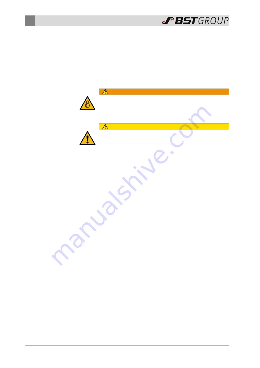
WARNING
Danger caused by trapping points between system components
and guide rollers!
Observe the following measures to avoid the danger. Otherwise,
there is a risk of severe injury or even death.
CAUTION
This work may only be performed by qualified personnel! (see
chapter
Qualification of the Personnel, page 13
)
5.1
General information
■
When selecting the installation site, please note that the scan-
ning point of the spectral measuring head may be at most 800
mm from the image center of the iPQ-Center camera.
■
It is possible for the length of the traverse bar to exceed the
distance between the side walls of the machine stand. In this
case it is necessary to guide the traverse bar out of the ma-
chine stand using e.g. a suitable cut-out. For further informa-
tion on guiding out the traverse bar, please refer to the mech-
anical drawings in the supplied customer documentation.
■
The scope of delivery of the color measuring system iPQ-Spec-
tral includes either a coated measuring roller or a motorized
backing unit with a traversing backing wheel, depending on the
system configuration. The printed web must be guided along
this measuring roller/backing wheel at the installation site of
the spectral measuring head. For further information on in-
stalling the measuring roller/backing wheel, please refer to the
manufacturer’s documentation (and the mechanical drawings
in the supplied customer documentation).


