background image

www.bssindustrial.co.uk

6

Introduction

The instructions are an integral part of the appliance and must be given to the end user on completion 

of the installation in order to comply with the current regulation.

It is important to carefully read the manual to understand all the information to enable safe installation, 

use and servicing. These instructions consist of details for installation, servicing, fault finding and 

replacement of parts for the cylinder purchased.

BSS will not accept any liability in the event of damage for not complying with the guidance in this 

instruction manual.

The instructions for this installation manual apply to the range of BSS BOSS™ Unvented Cylinders.

Safety is paramount when installing unvented hot water systems and the following instructions must 

be adhered to:

•  Only certified competant installers can install, commission and service the equipment supplied.

•  The cylinder must be used for potable hot water only. Any other applications will be considered 

incorrect use and BSS will not be held liable for any losses resulting from such use.

•  All installation and maintenance instructions must be observed to ensure the correct operation of 

the equipment.

•  The electric immersion must not be switched on unless the cylinder is completely full of water.

•  Domestic hot water may be stored at temperatures exceeding 60°C. Preventative measures 

should be put in place to negate the possibility of scalding.

•  A maintenance schedule should be put in place with a competent person to service the equipment 

annually to comply with the warranty conditions.

•  When servicing the system the mains supply to the cylinder should be isolated.

•  Only genuine spare parts should be used. A full list of items with relevant codes can be found on page 14.

The installation must be carried out by a person competent to install unvented hot water systems.

The installation must be carried out in accordance with the following recommendations:

All current Building Regulations issued by the Department of the Environment, i.e. Building Regulation 

G3 (England and Wales), Technical Standard P3 (Scotland) or Building Regulation P5 (Northern Ireland) 

and the Water Fitting Regulations (England and Wales) or Water Byelaws (Scotland). The installation 

should also be in accordance with the following British Standard Codes of Practice:

BS 5449:1990 Forced circulation hot water systems

BS 5546:2000 Installation of hot water supplies for domestic purposes

BS 5918:1989 Solar heating systems for domestic hot water

BS 6700:2006 Design, installation, testing and maintenance of services supplying water.

Failure to install this appliance correctly could lead to prosecution and will invalidate the guarantee. 

It is in your own interest and that of safety to ensure that the law is complied with.

Summary of Contents for BOSS 100

Page 1: ...rect Indirect Solar Unvented Cylinder Installation Maintenance Manual REGISTER THIS PRODUCT ONLINE WITHIN 28 DAYS OF COMMISSIONING IRELAND www joule ie register a product UNITED KINGDOM www jouleuk co uk register a product BSS DID INS 006 10 2017 ...

Page 2: ...ss Contact Tel Contact Email Installer Name Address Contact Tel Contact Email Product Product Installed Serial Number Installation Date Cylinder Located on cylinder badge I accept the terms and conditions in the installation manual MUST BE COMPLETED AND THEN REGISTERED ONLINE TO COMPLETE WARRANTY ...

Page 3: ...ervicing may be requested to prove that the unit has been serviced annually Unvented Kit Other Components The BOSS 25 year warranty covers BOSS cylinders installed in domestic properties against corrosion for a period of 25 years from the date of purchase All other components including valves expansion vessels immersion heaters fittings and controls are covered by a two year warranty from the date...

Page 4: ...www bssindustrial co uk 4 ...

Page 5: ...l Specification 20 Direct Technical Specification 22 Solar Technical Specification 24 Plumbing G3 Unvented Kit 25 Testing 26 Smart Control Immersion Setup 27 Immersion Installation 30 Cylinder Schematic S Plan 32 Cylinder Schematic Y Plan 34 Electronic Controls 35 Discharge Arrangement 38 Commissioning 39 Maintenance 41 Taking The Cylinder Out Of Use 42 Troubleshooting 44 Benchmark Checklist 46 Se...

Page 6: ...estic hot water may be stored at temperatures exceeding 60 C Preventative measures should be put in place to negate the possibility of scalding A maintenance schedule should be put in place with a competent person to service the equipment annually to comply with the warranty conditions When servicing the system the mains supply to the cylinder should be isolated Only genuine spare parts should be ...

Page 7: ...and connected to the earth line If plastic pipes are used they must be approved temperature resistant to 95 C at a pressure of 10bar A thermostatic mixer should be installed in the system to prevent the risk of scalding If there are leaks found in the system shut off the cold water stop valve from the main supply and contact a competent person immediately Also ensure to isolate the power going to ...

Page 8: ...tallation 1 5bar and 25ltr min should be regarded as the minimum The maximum mains pressure that the inlet control set can cope with is 10bar Change Of Water Supply The changing or alternating from one water supply to another can have a detrimental effect on the operation and or life expectation of the water heater storage cylinder pressure temperature relief valve and heating unit Where there is ...

Page 9: ...linder if this water heater is connected at anytime to a water supply where the TDS content of the water exceeds 600 mg L 16 In locations where TDS approaches 600 mg L e g due to sediment we strongly recommend fitting an appropriate filter to ensure water entering or in the water heater does not exceed this level at any time i e due to sediment build up Features Of The Unvented Cylinder Made from ...

Page 10: ...e ensures pressure compensation as a result of air flowing into the cylinder Connecting To The Cylinder All of the pipework connections on the cylinder are compression connection and female threaded Upon filling and commissioning ensure all connections are completely watertight No control or isolation valve should be fitted between the expansion relief valve and the storage cylinder The relief val...

Page 11: ...ppropriate for the type of tap etc Your aim should be to reduce the volume of the hot draw off pipework to a practical minimum so that the time taken for the hot water is as quick as possible Do not use monobloc mixer tap or showers if the balanced cold connection is not provided Outlets of this type can back pressurise the unit and result in discharge Expansion Vessel The expansion vessel receive...

Page 12: ...e installed on either horizontal or vertical pipework If it is mounted onto horizontal pipework the valve head must face upwards The direction of flow is marked on the body of the valve with arrows Thermostatic Mixer When installing a solar system with an unvented BSS BOSS twin coil cylinder a thermostatic mixing valve should be installed Its function is to act as an anti scald protection The ther...

Page 13: ... as a result of expansion of pipework over joists or where the pipe has been left touching other pipes or a part of the building structure Care must be taken to ensure that the pipework is correctly bracketed is not in tension or compression and does not carry the weight of components such as a circulation pump Setting The Hot Water Temperature The hot water temperature is set on the dual thermost...

Page 14: ...www bssindustrial co uk 14 34331116 34331127 34331160 34330830 34330948 34330937 34330896 19711233 19711244 19711255 34330863 34330852 34330701 Unvented Kit Components 19711436 19711266 Smart ...

Page 15: ...5 1971 1436 1971 1266 T P Valve 3433116 34331127 Tundish 34330948 34330937 Dual Stat 34330830 Prim Coil 2 P Z Valve 34330896 Unvented Kit Checklist Direct Indirect Inlet Control Group Inlet Control Group Tundish Tundish T P Valve fitted T P Valve fitted 3kW Immersion fitted 3kW Immersion fitted Expansion Vessel Expansion Vessel Dual Cylinder Stat 2 port Zone Valve ...

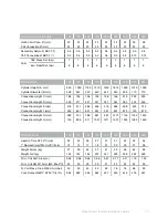
Page 16: ... C C C C C D Energy Efficiency 39 39 38 38 38 37 37 Ann el consumption kWh 2650 2654 2715 2719 2723 2764 4508 Sound Power Level dB 16 16 16 16 16 16 16 Thermostat Temp Set C 60 60 60 60 60 60 60 Daily En Usage Qelec kWh 24h 12 189 12 213 12 577 12 601 12 625 12 868 20 962 Nominal Capacity ltr 100 125 150 170 200 250 300 400 500 Indirect Solar Vertical Storage Volume V ltr 96 124 147 168 194 247 29...

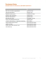
Page 17: ...MPa 4 bar T P relief valve setting 0 7MPa 90 C 7 bar Primary coil operating pressure max 0 6MPa 6 bar Immersion heater rating a c supply only single phase 3kW 50 60Hz Storage weights empty and full See Specification Tables Indirect coil ratings See Specification Tables Pressure drop across the indirect coils See Specification Tables Coil surface area See Specification Tables Technical Data Indirec...

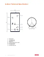
Page 18: ...Technical Specification 2 Boiler Return 3 Cold Water Inlet 7 Aquastat Pocket 8 Boiler Flow 9 Incoloy Immersion fact fitted 10 Secondary Return 13 T P Relief Valve 14 Hot Water Draw Off F C C D A B 13 10 9 8 7 3 2 E G H 14 15º 30º 9 3 30º ...

Page 19: ...0 400 500 Heat Up Time ΔT 50 C min 22 23 26 27 31 37 42 52 54 1º Re Heat time 70 dr off 15L m 12 14 17 18 21 25 29 37 38 Weight Empty kg 27 30 34 37 41 49 56 62 89 Weight Full kg 152 155 184 207 241 299 356 462 589 Prim Coil Surf Area m2 0 58 0 58 0 58 0 58 0 67 0 77 0 77 1 16 1 25 Prim Coil Rat 15L m kW 80 2ºC 20 20 20 20 21 23 23 25 26 Pr Coil Press Drop 60L hr mbar 45 45 45 45 65 76 76 88 90 Co...

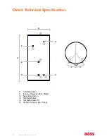
Page 20: ...uk 20 Direct Technical Specification D C A B 13 10 9 3 F G 14 15 E 30º 30º 10 3 3 Cold Water Inlet 9 Incoloy Immersion fact fitted 10 Secondary Return 13 T P Relief Valve 14 Hot Water Draw Off 15 Smart Immersion fact fitted ...

Page 21: ...s Safety 100 125 150 170 200 250 300 Hot Cold Conn Ø mm 22 22 22 22 22 22 22 Coil Connection Ø mm 22 22 22 22 22 22 22 Secondary Return Ø BSP F 0 5 0 5 0 5 0 5 0 5 0 5 0 5 T P Connection Ø BSP F 0 5 0 5 0 5 0 5 0 5 0 5 0 5 3bar T P Press Set bar 7 7 7 7 7 7 7 Exp Relief Set bar 6 6 6 6 6 6 6 Performance 100 125 150 170 200 250 300 Quantity Of Factory Fitted Immersions 2 Rating Of Factory Fitted Im...

Page 22: ...ler Return 3 Cold Water Inlet 7 Aquastat Pocket 8 Boiler Flow 9 Incoloy Immersion fact fitted 10 Secondary Return 13 T P Relief Valve 14 Hot Water Draw Off 15 Solar Sensor 16 Solar Boiler Flow 17 Solar Boiler Return I C C A B 13 10 9 8 7 3 2 H L L 14 K J G E D F 15 16 17 15 7 ...

Page 23: ...0L min 10 12 15 18 21 28 1º Re Heat time 70 draw off 15L min fr cold 45ºC 15 17 21 25 30 38 Weight Empty kg 38 45 54 60 68 95 Weight Full kg 208 245 304 361 468 593 Prim Coil Surf Area m2 0 58 0 58 0 64 0 64 0 77 0 77 Prim Coil Rating 60L min kW 20 20 21 21 23 23 Prim Coil Rat 15L m kW 80 2ºC 20 20 21 21 23 23 Prim Coil Press Drop 15L min mbar 45 65 76 76 88 90 Prim Coil Press Drop 60L min mbar 42...

Page 24: ...ncoming cold feed within 3m of cylinder Potable Expansion Vessel 2 must be fitted on cold feed between Inlet Valve 1 and cylinder Tundish 3 must be fitted on T P and P relief as shown in this diagram and also reference to page 43 45 Discharge Arrangement Failure to install unvented kit correctly invalidate warranty and does not comply with Building Regulations 1 3 2 1 2 3 Secondary Return ...

Page 25: ... Fitting The Immersion Heater Always check the immersion for signs of leakage before wiring commences The immersion heater must be completely submerged in water with a minimum of 200mm of water above the top of the immersion Do not operate the immersion heaters until the cylinder has been filled with water Wire the immersion through a double pole fused spur The contact separation must be no less t...

Page 26: ...tures through the day MANUAL works as standard mechanical thermostat can be set up to 70 C OPK off peak this must be selected when the cylinder is connected to the night tariff During the day time the immersion is not connected and this would require the smart control to be reset When OPK is selected it should be set at 60 C and working as a standard thermostat Alternatively the user can select th...

Page 27: ...fety Children should be supervised to ensure that they do not play with the appliance Thermostat Information The immersion heater is supplied with a T MEC 2 Electronic thermostat To maintain safety any thermostat replacement must be of the same type Low water temperature is recommended to reduce limestone deposit not lower than 60ºC The thermostat in this unit is able to disconnect both supply con...

Page 28: ...ency rating of the cylinder in which it is fitted OPK Basic Electronic Thermostat mode With the control knob turned on this position the thermostat will control water temperature to maximum 60 C and is unaffected by any interruption of power supply Use this position for manual switching or by timer such as economy type installations Antibacterial mode will function OFF In this mode the thermostat ...

Page 29: ... will function OFF In this mode the thermostat will not operate only the double pole safety cut out will function Antibacterial mode will NOT function Antifreeze mode This setting will maintaina minimum water temperature of 20 C to prevent the water heater from freezing Antibacterial mode will function MAX Maximum temperature in Manual Mode With the control knob turned clockwise to the MAX setting...

Page 30: ...ure Relief Valve 5 Isolation Valve not supplied 6 Exp Vessel with Wall Bracket 7 2 port Zone Valve one only supplied 9 Drain Valve not supplied 10 Tundish 11 Heating Circ Pump not supplied required with heat only boiler 7 7 1 2 9 3 5 6 10 4 11 Secondary Return Cold Main Hot Water Outlet Balanced Cold Connection High Limit Stat Boiler Prim Flow Boiler Prim Return Dual Stat ...

Page 31: ...Boss Direct Indirect Installation Guide 31 Cylinder Schematic Electrical Diagram S Plan ...

Page 32: ...tat Boiler Prim Flow Boiler Prim Return Dual Stat 1 Bronze Pump not supplied 2 Non Return Valve not supplied 3 Inlet Control Group 4 Temperature Pressure Relief Valve 5 Isolation Valve not supplied 6 Exp Vessel with Wall Bracket 7 2 port Zone Valve 8 3 port Valve not supplied 9 Drain Valve not supplied 10 Tundish 11 Heating Circ Pump not supplied required with heat only boiler ...

Page 33: ...Boss Direct Indirect Installation Guide 33 Cylinder Schematic Electrical Diagram Y Plan ...

Page 34: ... thermostats Always refer to manufacturers instructions which may override the detail in order to function correctly The operating thermostat which controls the temperature of the domestic hot water is adjustable A safety cut out is also incorporated within the thermostat and will operate at 85 C 3 C Both thermostats should run in series To reset the safety cut out and the motorised valve the rese...

Page 35: ...om the tundish should terminate in a safe place where there is no risk to persons in the vicinity of the discharge be of metal and Be at least one pipe size larger than the nominal outlet size of the safety device unless its total equivalent hydraulic resistance exceeds that of a straight pipe 9m long i e discharge pipes between 9m and 18m equivalent resistance length should be at least two sizes ...

Page 36: ... i e in dwellings occupied by blind infirm or disabled people consideration should be given to the installation of an electronically operated device to warn when discharge takes place Worked Example The example on the next page is for G1 2 temperature relief valve with a discharge pipe D2 having 4 No elbows and length of 7m from the tundish to the point of discharge Maximum resistance allowed for ...

Page 37: ...raight into a soil pipe Safety Device temperature relief valve Metal discharge pipe D2 from temperature relief valve to tundish Minimum 300mm Maximum 600mm Tundish Discharge below fixed grating Building Regulation G3 section 3 61 gives alternative points to of discharge Trapped Gulley Fixed Grating Metal discharge pipe D2 from tundish with continuous fall See Building Regulation G3 section 3 56 Ta...

Page 38: ...to ensure that all flux residues are removed from the system Indirect Units Fill the primary circuit according to the boiler manufacturers commissioning instructions Any additives used in the heating system water circulating through the cylinder coil must be compatible for use with stainless steel cylinders Ensure the lever on the two port valve is set to the filling position When full move the le...

Page 39: ...ler service Twist the cap of the expansion relief valve on the inlet control set and allow water to flow for 5 seconds Release and make sure it resets correctly Repeat with the pressure temperature relief valve In both cases check that the discharge pipework is carrying the water away adequately If not check for blockages etc and clear Check that any immersion heaters fitted are working correctly ...

Page 40: ...nspection Where internal inspection of the cylinder is required an endoscope can be used Inspection can be carried out by draining down the cylinder and removing a component that is fitted to a wet connection in the cylinder Safety Valve Checks Water discharges from either the temperature pressure relief valve or the expansion relief valve indicates a problem Check your discharge pipework is free ...

Page 41: ... of a problem please contact your installer and the contact details in this installation manual Log Book The installer must comply with all of the installation instructions contained within this installation manual On completion of the initial installation and after each subsequent annual service the Benchmark Log Book must be completed and signed by the competent person who has worked the unit Th...

Page 42: ...s flowing from the safety valves through the tundish this indicates a fault condition and action is needed If this water is hot turn the boiler and or the immersion heater off Do not turn off the water until the discharge runs cool The discharge may also stop CALL OUT A COMPETENT PLUMBER TO SERVICE THE UNIT Tell them you have a fault on an unvented cylinder We stock all the spare parts they may ne...

Page 43: ...essure in expansion vessel Recharge to 3 bar if necessary If bladder perished replace vessel Unit is being back pressurized With cylinder cold check pressure in cylinder If this is the same as the incoming mains pressure then you are getting backfeed Install a balanced cold supply Water discharges from temperature pressure relief valve Unit has overheated thermal controls have failed Switched off ...

Page 44: ...www bssindustrial co uk 44 48 Direct Indirect Mains Pressure Benchmark Checklist ...

Page 45: ...Boss Direct Indirect Installation Guide 45 49 Water Storage System Commisioning ...

Page 46: ...mpany Name Telephone No Comments Signature Service 1 Date Engineer Name Company Name Telephone No Comments Signature Service 1 Date Engineer Name Company Name Telephone No Comments Signature Service 1 Date Engineer Name Company Name Telephone No Comments Signature Service 1 Date Engineer Name Company Name Telephone No Comments Signature Service 1 Date Engineer Name Company Name Telephone No Commen...

Page 47: ...Boss Direct Indirect Installation Guide 47 Notes ...

Page 48: ...www bssindustrial co uk 48 BSS DID INS 006 10 2017 The BSS Group Ltd BOSS Court 7 Barton Close Enderby Leicester LE19 1SJ ...

Reviews: