2
GENERAL
These installation instructions cover the 580J units with gas
heat and electric cooling. Units are pre-wired and pre-charged
with environmentally sound Puron
®
(R-410A) refrigerant at
the factory. See Fig. 1 for model number nomenclature. See
Fig. 2-4 for unit dimensions. See Fig. 5 and 6 for service
clearances.
Rated Indoor Airflow (cfm)
Table 1 lists the rated indoor airflow used for the AHRI
efficiency rating for the units covered in this document.
Table 1 — AHRI Efficiency — Rated Indoor Airflow
Pre-Installation
Complete the following checks before installation.
1. Consult local building codes and the NEC (National
Electrical Code) ANSI/NFPA 70 for special installa-
tion requirements.
2. Determine unit location (from project plans) or select unit
location.
3. Check for possible overhead obstructions which may in-
terfere with unit lifting or rigging.
WARNING
CARBON-MONOXIDE POISONING HAZARD
Failure to follow instructions could result in severe person-
al injury or death due to carbon-monoxide poisoning, if
combustion products infiltrate into the building.
Check that all openings in the outside wall around the vent
(and air intake) pipe(s) are sealed to prevent infiltration of
combustion products into the building.
Check that furnace vent (and air intake) terminal(s) are not
obstructed in any way during all seasons.
CAUTION
Failure to follow this caution may result in personal injury.
Sheet metal parts may have sharp edges or burrs. Use care
and wear appropriate protective clothing, safety glasses and
gloves when handling parts and servicing air conditioning
equipment.
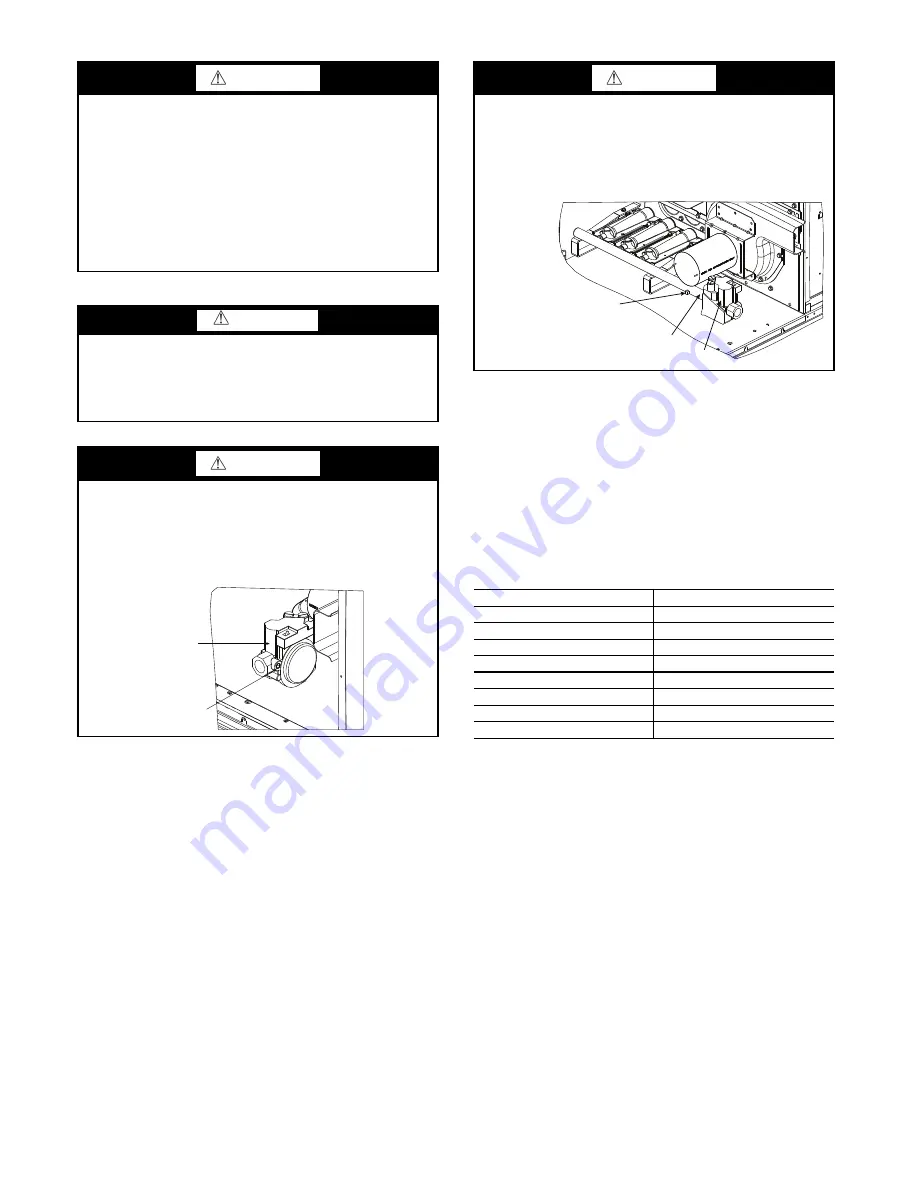
WARNING
FIRE HAZARD
Failure to follow this warning could result in personal
injury, death, and/or property damage.
Inlet pressure tap set screw must be tightened and
1
/
8
in. NPT
pipe plug must be installed to prevent gas leaks.
GAS VALVE
INLET PRESSURE
TAP SET SCREW
WARNING
FIRE HAZARD
Failure to follow this warning could result in personal
injury, death, and/or property damage.
Manifold pressure tap set screw must be tightened and
1
/
8
in. NPT pipe plug must be installed to prevent gas leaks.
MODEL NUMBER
FULL LOAD AIRFLOW (CFM)
580J*08N/P
2,400
580J*08D/F/K/M
2,250
580J*09N/P
3,000
580J*09D/F/K/M
3,400
580J*12N/P
3,400
580J*12D/F/K/M
3,000
580J*14D/F/K/M
3,600
580J*16D/F/K/M
5,250
MANIFOLD
GAS VALVE
MANIFOLD PRESSURE
TAP SET SCREW
Summary of Contents for 580J*16D Series
Page 4: ...4 Fig 2 Unit Dimensional Drawing Sizes 08 09 and 12 ...
Page 5: ...5 Fig 2 Unit Dimensional Drawing Sizes 08 09 and 12 cont ...
Page 6: ...6 Fig 3 Unit Dimensional Drawing Size 14 ...
Page 7: ...7 Fig 3 Unit Dimensional Drawing Size 14 cont ...
Page 8: ...8 Fig 4 Unit Dimensional Drawing Size 16 ...
Page 9: ...9 Fig 4 Unit Dimensional Drawing Size 16 cont ...
Page 15: ...15 Fig 9 580J 16 Roof Curb Details ...
Page 32: ...32 Fig 58 580J 08 14 Typical Perfect Humidity Dehumidification System Humidistat Wiring ...
Page 33: ...33 Fig 59 580J 16 Typical Perfect Humidity Dehumidification System Humidistat Wiring ...
Page 48: ...48 Fig 67 580J 08 12N P Typical RTU Open System Control Wiring Diagram ...
Page 49: ...49 Fig 68 580J 08 14 Typical RTU Open System Control Wiring Diagram ...
Page 50: ...50 Fig 69 580J 16 Typical RTU Open System Control Wiring Diagram ...
Page 52: ...52 Fig 71 580J 16 Typical RTU Open System Control Wiring Diagram with Perfect Humidity System ...


