


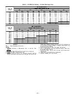


Table 10 — 551B036 Air Delivery — Horizontal Discharge Units
AIRFLOW
(Cfm)
BELT-DRIVE MOTOR
External Static Pressure (in. wg)
0.1
0.2
0.3
0.4
0.5
0.6
Rpm
Bhp
Rpm
Bhp
Rpm
Bhp
Rpm
Bhp
Rpm
Bhp
Rpm
Bhp
900
526
0.06
584
0.08
656
0.12
734
0.22
818
0.25
875
0.27
1000
570
0.09
627
0.13
738
0.19
800
0.26
848
0.29
895
0.31
1100
614
0.13
670
0.16
758
0.23
812
0.29
863
0.32
914
0.35
1200
658
0.16
710
0.23
780
0.28
840
0.32
889
0.36
938
0.40
1300
703
0.20
752
0.27
808
0.32
868
0.37
916
0.41
963
0.45
1400
725
0.29
776
0.31
845
0.38
891
0.42
937
0.47
983
0.51
1500
755
0.33
816
0.38
870
0.43
924
0.48
969
0.53
1014
0.58
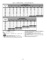
AIRFLOW
(Cfm)
BELT-DRIVE MOTOR
External Static Pressure (in. wg)
0.7
0.8
0.9
1.0
1.1
1.2
Rpm
Bhp
Rpm
Bhp
Rpm
Bhp
Rpm
Bhp
Rpm
Bhp
Rpm
Bhp
900
924
0.32
953
0.35
989
0.38
1028
0.42
1074
0.49
1120
0.54
1000
936
0.35
977
0.39
1020
0.44
1064
0.48
1124
0.54
1185
0.60
1100
960
0.39
1005
0.43
1052
0.49
1100
0.52
1163
0.59
1225
0.65
1200
960
0.45
1038
0.50
1076
0.53
1136
0.59
1201
0.65
1266
0.72
1300
1012
0.51
1061
0.56
1090
0.61
1172
0.65
1239
0.72
1306
0.79
1400
1027
0.56
1071
0.60
1108
0.67
1208
0.70
1278
0.79
1347
0.87
1500
1056
0.63
1097
0.68
1117
0.70
1245
0.74
1315
0.87
1385
0.96
LEGEND
Bhp — Brake Horsepower Input to Fan
NOTES:
1. Boldface
indicates
a
field-supplied
drive
is
required.
(See
Note 4.)
2. Maximum continuous bhp is 1.20. Extensive motor and electrical test-
ing on these units ensures that the full range of the motor can be
utilized with confidence. Using your fan motors up to the ratings shown
will not result in nuisance tripping or premature motor failure. Unit
warranty will not be affected.
3. Values include losses for filters, unit casing, and wet coils.
4. Motor drive range: 760 to 1090. All other rpms require field-supplied
drive.
5. Interpolation is permissible. Do not extrapolate.
6. Use of a field-supplied motor may affect wire sizing. Contact your
local representative to verify.
7. Minimum allowable cfm is 300 cfm/ton.
—25—
Summary of Contents for 551B Series
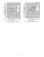
Page 32: ...Fig 34 Cooling Charging Chart 551B060 Fig 35 Cooling Chart Chart 551B072 32 ...
Page 37: ......
Page 38: ......
Page 39: ......


