


NOTES:
1. Dimensions in [
] are in millimeters.
2.
Center of gravity.
3.
Direction of airflow.
4. Ductwork to be attached to accessory roof curb only.
5. Minimum clearance (local codes or jurisdiction may prevail):
a. Bottom to combustible surfaces (when not using curb), 0 in., on horizontal
discharge units with electric heat 1 in. clearance to ductwork for 1 ft.
b. Condenser coil, for proper airflow, 36 in. one side, 12 in. the other. The side
getting the greater clearance is optional.
c. Overhead, 60 in. to assure proper condenser fan operation.
d. Between units, control box side, 42 in. per NEC (National Electrical Code).
e. Between unit and ungrounded surfaces, control box side, 36 in. per NEC.
f. Between unit and block or concrete walls and other grounded surfaces, con-
trol box side, 42 in. per NEC.
g. Horizontal supply and return end, 0 inches.
6. With the exception of the clearance for the condenser coil and combustible
surfaces as stated in notes 5a, b, and c, a removable fence or barricade re-
quires no clearance.
7. Units may be installed on combustible floors made from wood or class A, B, or
C roof covering material.
8. The vertical center of gravity is 1
8
-6
1
⁄
2
9
[470] up from the bottom of the base
rail.
UNIT
STD. UNIT WEIGHT
VARISLIDE™
ECONOMIZER WEIGHT
CORNER WEIGHT (A)
CORNER WEIGHT (B)
CORNER WEIGHT (C)
CORNER WEIGHT (D)
Lb
Kg
Lb
Kg
Lb
Kg
Lb
Kg
Lb
Kg
Lb
Kg
551B036
435
197
34
15.4
124
56.2
106
48.1
95
43.1
110
49.9
551B048
445
202
34
15.4
127
57.6
108
49.0
97
44.0
113
51.3
551B060
465
211
34
15.4
133
60.3
113
51.3
101
45.8
118
53.5
551B072
520
236
34
15.4
149
67.6
127
57.6
112
50.8
132
59.9
CONNECTION SIZES
A
1
3
⁄
8
9
dia. [35] field power supply hole
B
2
9
dia. [51] power supply knock-out
C
1
3
⁄
4
9
dia. [44] charging port hole
D
7
⁄
8
9
dia. [22] field control wiring hole
E
3
⁄
4
9
-14 NPT condensate drain
F
2
1
⁄
2
9
dia. [64] power supply knock-out
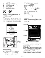
Fig. 2 — Base Unit Dimensions
—2—
Summary of Contents for 551B Series
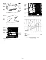
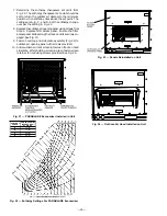
Page 32: ...Fig 34 Cooling Charging Chart 551B060 Fig 35 Cooling Chart Chart 551B072 32 ...
Page 37: ......
Page 38: ......
Page 39: ......


