


Remove burner by loosening mounting nuts and turn oil burner
slightly counterclockwise to unlock the key hole burner flange.
Prevent putting undue strain on burner wiring. (It may be neces-
sary to disconnect burner wiring in some cases.)
To reinstall burner, insert on the four burner studs on key hole
burner flange and turn it clockwise to lock it and tighten nuts.
IMPORTANT: Burner must always be installed in the upright
position with ignition control on top.
J.
Filters
WARNING:
Never operate unit without a filter or with
filter access door removed. Failure to adhere to this
warning could lead to a hazardous condition which could
lead to equipment damage and bodily harm.
An external filter rack is provided as standard equipment with
furnace. A sufficient clearance should be provided for air filter
access. Refer to Table 8 for filter rack flange dimensions for return
air duct.
START-UP, ADJUSTMENT, AND SAFETY CHECKOUT
I.
OPERATIONAL CHECKOUT
WARNING:
DO NOT TAMPER WITH UNIT OR
CONTROLS—CALL YOUR SERVICE TECHNICIAN.
Installation of furnace is now complete. Run through the following
checkout and ensure each item has been performed.
1. Correct nozzle size has been selected for desired input rate.
2. Blower wheel support is removed.
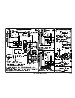
3. Electrical wiring is completed according to Fig. 3 or Fig. 4.
4. Blower access door is secured in place.
5. Valve on oil supply line is open.
6. RESET BUTTON on primary control is pushed down.
7. Flame observation door and 2 cleanout access doors located
at front of unit are closed.
8. Thermostat is set for heating mode and set above room
temperature.
If all of the above items have been performed, set main electrical
switch to ON position and burner should start. When burner starts,
proceed to Combustion Check section.
II.
COMBUSTION CHECK
In order to obtain optimum performance from oil burner, the
following setup procedures must be followed:
1. A test kit to measure smoke, stack draft, over-fire draft, oil
pump pressure, CO
2
, and stack temperatures MUST be used
in order to obtain proper air band setting. Although all of
the above measurements are required for optimum setup
and efficiency data, the most important readings that must
be taken are smoke number, over-fire draft, stack draft, and
pump pressure.
2. The proper smoke number has been established by engi-
neering tests to be between 0 and 1. This degree of smoke
emission is commonly referred to as a
″
trace
″
of smoke. It
is recommended to use a Bacharach true spot smoke test set
or equivalent.
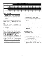
3. In order to ensure proper draft through furnace, a baromet-
ric draft regulator (supplied with furnace) must be installed.
In order for this device to function properly, barometric damper
must be mounted with hinge pins horizontal and face of damper
vertical. (See instructions included with damper.) The draft regu-
lator should be adjusted after furnace has been firing for at least 5
minutes, and set between -0.025 and -0.035 in. wc. (See Table 9.)
4. The over-fire draft, which is taken through observation door
(located in center line above burner in front panel of
furnace), is a measurement necessary to determine if there
is a blockage between oil burner and flue outlet.
There should be a total pressure drop of between 0.020 and 0.05 in.
wc through furnace as shown in Table 9. The over-fire draft must
be set within the range shown in Table 9.
A reading outside the range shown in Table 9 (for e0.1 in.
wc) would indicate that furnace is in an extremely high-pressure
condition in primary section. This condition may be caused by any
of the following problems:
a. Excessive combustion air due to air shutter being too
wide open.
b. A lack of flue draft (chimney effect) or some other
blockage, such as soot, in secondary section of heat
exchanger.
c. Use of an oversized nozzle input.
d. Pump pressure over values listed in Table 10.
5. The CO
2
and stack temperature instruments enable you to
obtain data required to determine thermal efficiency of
furnace.
6. An oil filter should be installed as close to burner as
possible with ALL oil burners and is essential on lower
firing rate burners. We recommend the use of a low
pressure drop oil filter such as the General Filter, Inc. model
#1A-25A or equivalent.
7. The oil pressure regulator is factory set to give oil pressure
of 135 psig for the model having 105,000 BTUH input and
135 psig for the model haveing 119,000 BTUH input. The
firing rate noted on nameplate may be obtained using the
nozzles and pump pressures indicated in table #5. The
proper oil burner turbulator setting for all the firing rates
is 0 (zero).
8. On a new installation, air entrapped in oil line leading from
tank to nozzle must be thoroughly purged in order to
prevent excessive after drip. The oil pump is provided with
a special fitting which allows purging of any air between
tank and oil pump. The proper procedure for performing
this operation is as follows:
a. Place a piece of clear plastic 1/4 in. diameter tubing over
purge fitting on oil pump.
b. Start oil burner, then open purge fitting and allow burner
to run until purge tube is completely free of air bubbles.
c. Tighten purge fitting. Allow oil to run to nozzle and fire
burner.
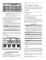
TABLE 8—FILTER AND FLANGE (IN.)
UNIT
SIZE
AIR FILTER
SIZE
FLANGE OPENING
SIZE
036105
16 X 24 X 1
or
16 X 25 X 1
15 X 23
060120
20 X 30 X 1
19 X 29
TABLE 9—FURNACE DRAFT CONDITIONS (IN. WC)
FURNACE
INPUT
(BTUH)
FLUE
DRAFT
MINIMUM
OVER-FIRE
DRAFT
MAXIMUM
TOTAL RESTRICTION
THROUGH
HEAT EXCHANGER
70,000
-0.025
0.010
0.020 to 0.035
91,000
-0.025
0.020
0.030 to 0.045
105,000
-0.025
0.025
0.035 to 0.050
119,000
-0.025
0.025
0.035 to 0.050
140,000
-0.025
0.025
0.035 to 0.050
154,000
-0.025
0.025
0.035 to 0.050
—7—


