


31
ZTKS0213 / Z31939 / Rev.: 01
Operation
5.2.3
Rebuilding Vacuum
Precondition
•
Vacuum valve mounted.
Procedure
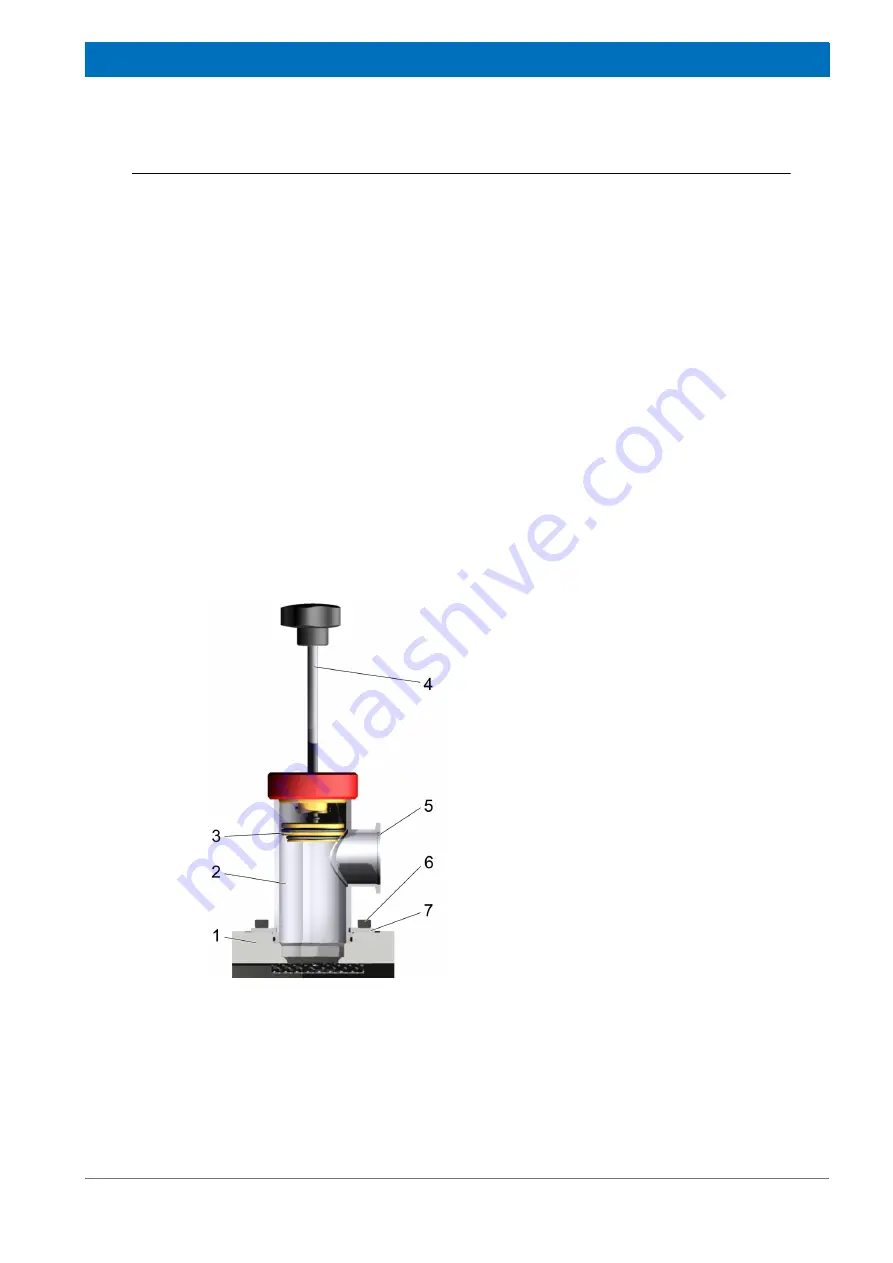
Figure 5.5:
Rebuilding vacuum
1.
Use the KF connector to connect the
vacuum pumping unit with the KF
40
flange (5) of the vacuum valve (2). Use a
short pumping line with a large diameter.
2.
Evacuate the vacuum valve and the
pumping line to a pressure of better than
5 x 10
-5
mbar.
3.
Pull out the valve stem (4) of the valve body
to release the sealing plug out of the top
plate (1). The sealing plug (3) snaps into
place. The snapping is well defined and will
be heard and felt. The cryostat is open after
this procedure.
4.
Continue generating vacuum of better than
1 x 10
-4
mbar (up to 2 –3 hours).
5.
Start cool down procedure (see section
6.
When the system has reached base temper-
ature push the valve stem (4) slightly into
the valve operator body (2) to insert the
sealing plug (3) into its seat in the top
plate (1). The sealing plug snaps in. The
snapping is well defined and will be heard
and felt.
7.
Stop pumping.
8.
Vent the pumping line.
9.
Disconnect the turbomolecular pump.
10. Remove the vacuum valve (see
Summary of Contents for EPR 12T Cryogen Free
Page 1: ...Version Innovation with Integrity EPR 12T Cryogen Free 01 User Manual EPR Spectroscopy ...
Page 6: ...6 ZTKS0213 Z31939 Rev 01 Contact ...
Page 25: ...25 ZTKS0213 Z31939 Rev 01 4 Assembling Approved persons Bruker Service only ...
Page 26: ...26 ZTKS0213 Z31939 Rev 01 Assembling ...
Page 48: ...48 ZTKS0213 Z31939 Rev 01 Operation ...
Page 54: ...54 ZTKS0213 Z31939 Rev 01 Maintenance ...
Page 55: ...55 ZTKS0213 Z31939 Rev 01 8 Disassembling Approved persons Bruker Service only ...
Page 56: ...56 ZTKS0213 Z31939 Rev 01 Disassembling ...
Page 58: ...58 ZTKS0213 Z31939 Rev 01 Warning Signs ...
Page 60: ...60 ZTKS0213 Z31939 Rev 01 List of Figures ...
Page 62: ...62 ZTKS0213 Z31939 Rev 01 List of Tables ...
Page 64: ...64 ZTKS0213 Z31939 Rev 01 Glossary ...
Page 80: ...Bruker Corporation info bruker com www bruker com Order No Z31939 ...