CHAPTER
8
Quick
Setup
Guide
49
8) Open the
Measured data
task and check the
Remote Station
component. On the
Server control
tab page check the
Server status
to confirm that it is running and
the following fields:
a) Broadcast IP
b) Listen on TCP port
c) Remote UDP port
are all configured according to the instructions given in the Pass-by help.
9) Start the Remote Station server if it is not already started.
The Ground Station is now configured, move to the Vehicle Station.
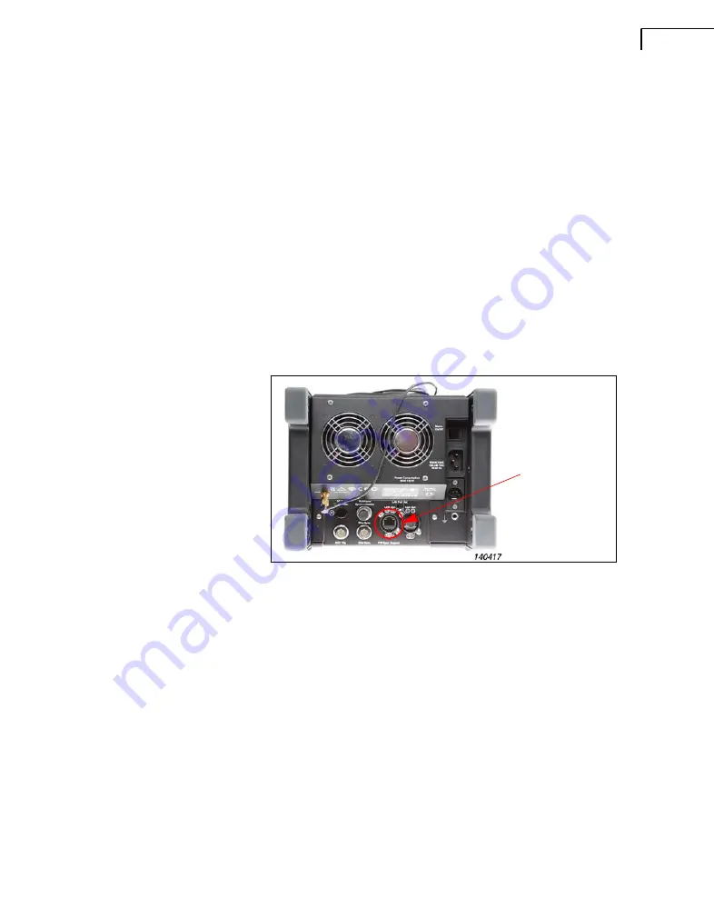
10) Connect the Vehicle Station PC to the Vehicle Station front end using a Cat. 6 LAN
patch cable.
Fig.8.3
Connecting
the
LAN
cable
to
the
front
end
11) Connect the GPS antenna at the rear of the front end frame and make sure that the
antenna is located with a line of sight to the sky. This can be through a window, as the
antenna is very sensitive.
12) Switch on the front end using the Mains On/Off switch at the rear of the frame.
13) Check that the display on the Input Module says “GPS Locked” to confirm that it is
ready to use GPS sync for the measurements.
14) Start the Vehicle Station PC and open the
PBY Vehicle Pass-by
software module.
15) Use the
Reconnect Signals
feature if necessary to make sure that the signals defined
in the template are connected to the correct measurement channels.
16) In the
Acquisition Setup
task, use the radio button to select the
Multivehicle
mode.
17) Configure all parameters according to the instructions found in the software Help.
18) Select a standard for testing and create a session in the
Session Setup
task.
Attach
the
LAN
cable
on
the
rear
of
the
frame
The
PoE
switch
is
above
this
socket
Summary of Contents for PULSE 7788
Page 2: ......
Page 3: ...BE 1716 14 September 2015 PULSE Vehicle Pass by Test Systems Installation Manual ...
Page 10: ...PULSE Vehicle Pass by Test Systems Installation Manual 4 ...
Page 50: ...PULSE Vehicle Pass by Test Systems Installation Manual 44 ...
Page 60: ...PULSE Vehicle Pass by Test Systems Installation Manual 54 ...
Page 61: ......


