PULSE Multi-analyzer System Type 3560-B/C/D/E –
Installation and IDAe Hardware
24
In order to physically update the IP address of the Type 3560-B/C/D/E front-end, you must
connect the supplied cable AO-1451 between the RS
−
232 port on the LAN Interface Module
(the controller module) and a COM port on your PC. Fig.2.14 shows the position of the
RS
−
232 connector on the front-end. If you know which COM port you have used, you may
select this from the list named
Choose COM port
. Choosing ‘Automatic’ prompts the
program try all available COM ports, one after the other.
When connection has been established, click
Next
to change the address. At this point the
IP address will be changed and the front-end will reboot. Then the LAN connection between
the front-end and the PC will be tested for valid communication.
If the RS
−
232 communication with the front-end fails, the Setting Front-end IP Address
page will show ‘Access denied’. The RS
−
232 communication failed either due to a missing
connection or due to the front-end not having been powered up. You can try setting the IP
address once more by clicking
Next
.
If the change of IP address succeeds, the front-end reboots, and the program waits while
trying to establish a connection using the new IP address. If this fails and the front-end is
powered-on and connected to the network, the typical cause is mismatch of front-end IP
address and PC IP address (see the warning following Fig.2.11).
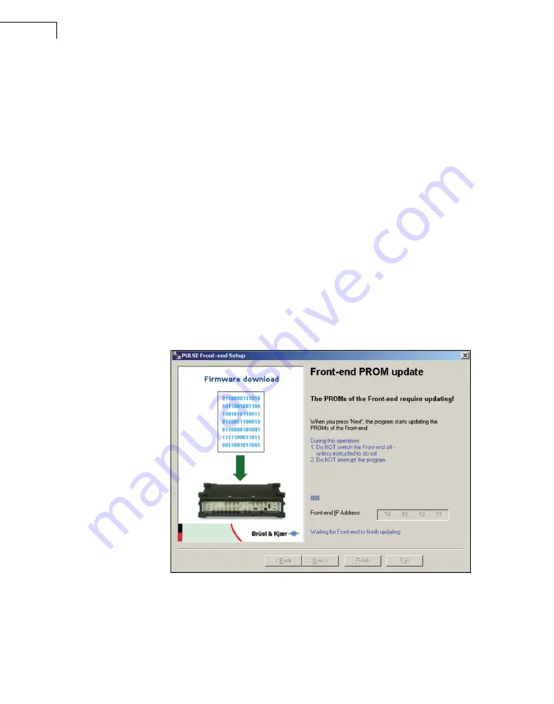
When the connection succeeds, the setup program checks the firmware versions of the front-
end. If an update of the front-end firmware is required, Fig.2.15 is displayed:
Fig.2.15
PROM update page
The Flash PROM update will start when you click on
Next
. During this update
−
which
takes several minutes
−
you must not interrupt the program and/or power-off the front-end,
unless the program tells you to. A progress indicator is displayed.
When the update is complete, or when no firmware update is necessary, the program
presents the final page (Fig.2.16).
Summary of Contents for PULSE 3560-B
Page 2: ......
Page 8: ......
Page 11: ...Part I Installation...
Page 12: ......
Page 44: ...PULSE Multi analyzer System Type 3560 B C D E Installation and IDAe Hardware 36...
Page 53: ...Part II Hardware...
Page 54: ......
Page 110: ...PULSE Multi analyzer System Type 3560 B C D E Installation and IDAe Hardware 102...
Page 140: ...PULSE Multi analyzer System Type 3560 B C D E Installation and IDAe Hardware 132...
Page 142: ...PULSE Multi analyzer System Type 3560 B C D E Installation and IDAe Hardware 134...
Page 143: ...Part III Appendices...
Page 144: ......
Page 148: ...PULSE Multi analyzer System Type 3560 B C D E Installation and IDAe Hardware 140...
Page 161: ......


