


III-42
(5)
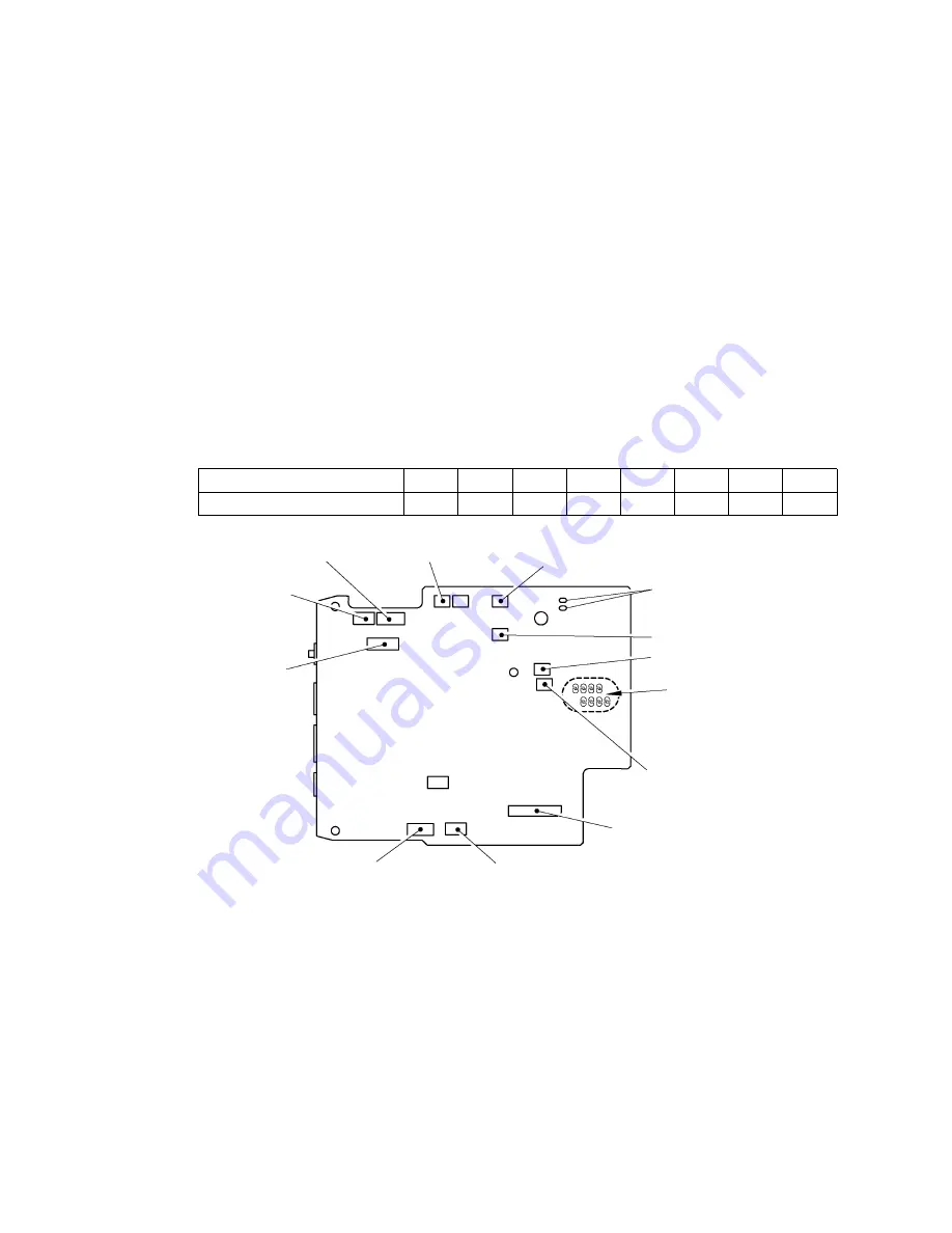
Set the connectors and the cables shown in the figure below.
- Head flexible cable
- Full cutter sensor connector
- Sensor PCB harness
- Half cutter sensor connector
- Sub PCB connector
- Eject motor lead wire
- Tape feed motor connector
- Release motor connector
- Full cutter motor connector
- Roller holder sensor connector
- Half cutter motor connector
- Tape end sensor connector
(6)
Solder two lead wires of the eject motor ASSY.
Note1: When replacing the thermal head, change the solder point on the main PCB
according to the resistance value of the thermal head. When the solder point is
changed, verify with a multi meter whether solder on the unsolder point is removed
properly.
Note2: Be sure to use the lead-free solder. (Set the temperature of the solder iron to 350
°
C.)
<Resistance values of the head and corresponding solder points>
Resistance value of the head
L
A
B
C
D
E
F
S
Solder point
L
A
B
C
D
E
F
S
Fig. 3.1-72 Reassembling of the Connectors and the Cables
Half cutter sensor connector
Soldered points of eject motor
Full cutter sensor connector
Half cutter motor connector
Solder point
Full cutter motor connector
Head flexible cable
Roller holder sensor connector
Tape feed motor connector
Sub PCB connector
Tape end sensor connector
Sensor PCB harness
Release motor connector
Summary of Contents for PT-9500PC - P-Touch 9500pc B/W Thermal Transfer Printer
Page 1: ...SERVICE MANUAL MODEL PT 9500PC ...
Page 2: ...SERVICE MANUAL MODEL PT 9500PC ...
Page 86: ...IV 10 3 The LED does not turn on 4 No printing is performed ...
Page 87: ...IV 11 5 The interface malfunction 6 The tape is not cut ...
Page 88: ...IV 12 7 The tape is not fed correctly ...
Page 89: ...IV 13 ...
Page 90: ...IV 14 8 Half cut failure ...
Page 91: ...IV 15 9 Forced tape eject failure ...
Page 92: ...IV 16 10 The failure of pressure contact release of the roller holder ...
Page 103: ......
Page 104: ......
Page 105: ......