


III-40
[ 11 ]
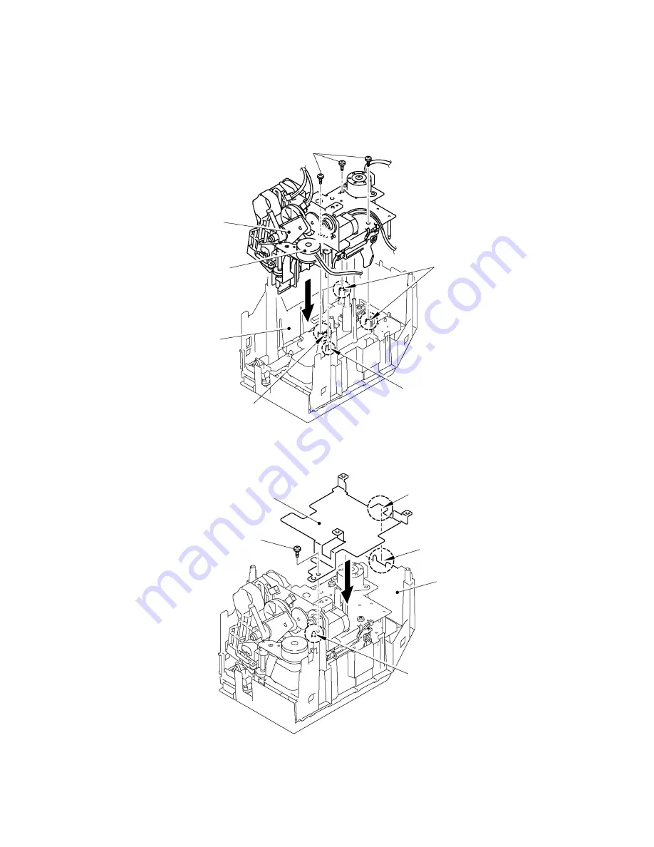
Reassembling of the Printing Mechanical Unit, the Shield Plate B and the Main PCB ASSY
(1)
Set the printing mechanical unit on the three positioning bosses approaching from the right
overhead of the body cover. Be sure not to nip the harnesses and connectors at this time.
Secure it with three screws.
(2)
Engage the harness of the eject motor with the hook on the body cover.
Fig. 3.1-69 Reassembling the Printing Mechanical Unit
(3)
Set the shield plate B adjusting to the positioning bosses and the square hole for the USB IF
and secure it with a screw.
Fig. 3.1-70 Reassembling the Shield Plate B and the Main PCB ASSY
Screws
Positioning bosses
Hook
Positioning boss
Body cover
Eject motor
Printing mechanical unit
Positioning boss
Square hole for the USB IF
Body cover
Positioning boss
Screw
Shield plate B
Summary of Contents for PT-9500PC - P-Touch 9500pc B/W Thermal Transfer Printer
Page 1: ...SERVICE MANUAL MODEL PT 9500PC ...
Page 2: ...SERVICE MANUAL MODEL PT 9500PC ...
Page 86: ...IV 10 3 The LED does not turn on 4 No printing is performed ...
Page 87: ...IV 11 5 The interface malfunction 6 The tape is not cut ...
Page 88: ...IV 12 7 The tape is not fed correctly ...
Page 89: ...IV 13 ...
Page 90: ...IV 14 8 Half cut failure ...
Page 91: ...IV 15 9 Forced tape eject failure ...
Page 92: ...IV 16 10 The failure of pressure contact release of the roller holder ...
Page 103: ......
Page 104: ......
Page 105: ......