III
- 12
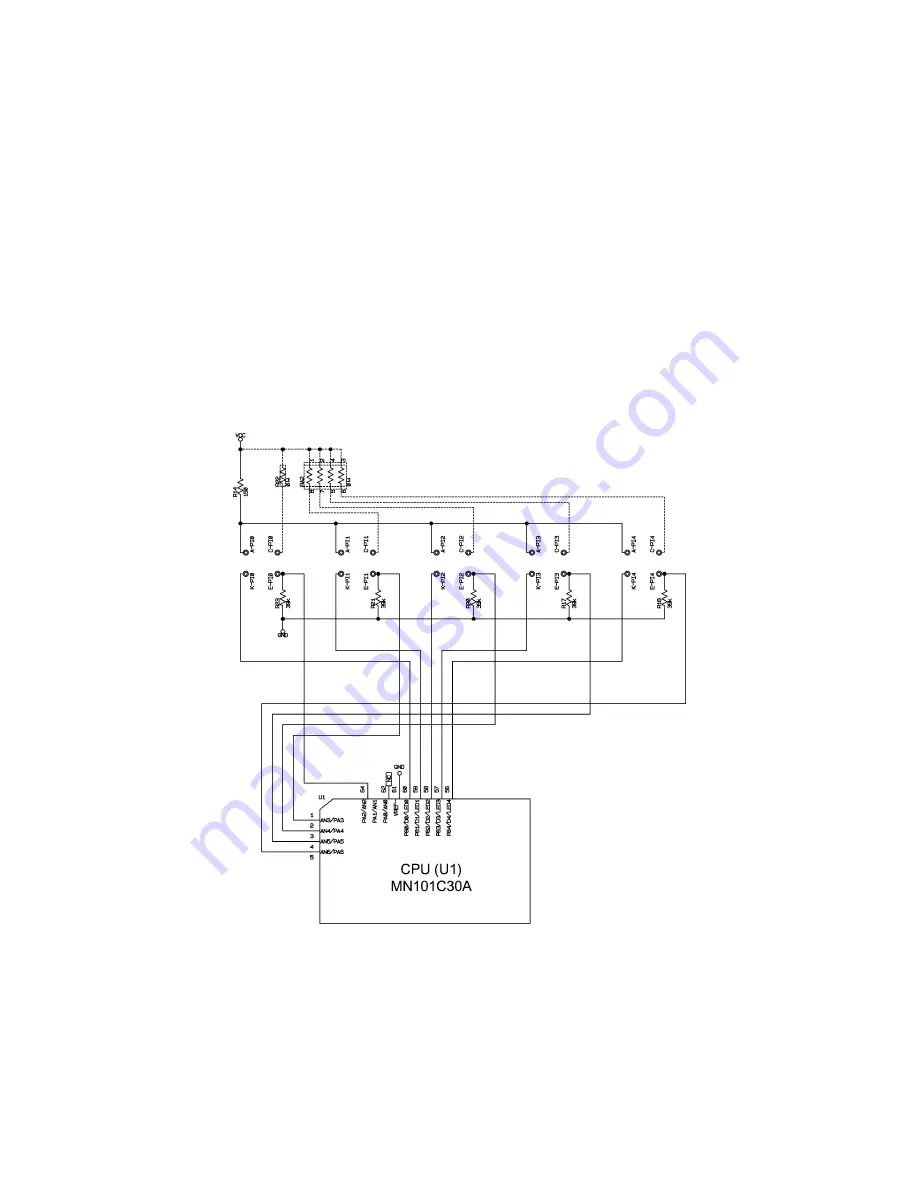
3.2.11 Dial Position Detection Circuit
Dial LED scanning
Figure 3.2-15 shows the LED scan circuit that detects the dial position.
The CPU scans five LEDs. Ports LED0 through LED4 on the CPU issue a group of LED
scanning pulses. Port AN2 through AN6 act as input ports that receive LED status.
Scanning timing
The CPU turns ports LED0, LED1, LED2, LED3, and LED4 Low in this order. When not
Low, those ports are High or in high impedance. When a particular port out of them is
Low, the CPU reads the status of the corresponding port.
The CPU scans those LEDs every 50 ms. If the CPU reads the same pattern on input
ports five successive times, then it interprets it as the current dial position.
Figure 3.2-16 shows the waveforms of dial LED scanning pulse outputs.
Figure 3.2-15 Dial Position Detection Circuit
Summary of Contents for P-touch BB4
Page 1: ...SERVICE MANUAL MODEL P touch BB4 ...
Page 2: ...SERVICE MANUAL MODEL P touch BB4 ...
Page 5: ...Chapter I SPECIFICATIONS ...
Page 9: ...I 3 Figure 1 1 2 Key Arrangement 1 ...
Page 10: ...I 4 Figure 1 1 2 Key Arrangement 2 ...
Page 12: ...Chapter II MECHANISMS ...
Page 42: ...Chapter III ELECTRONICS ...
Page 54: ...III 11 Figure 3 2 14 Waveforms of Control Signal and Motor Drive Current ...
Page 56: ...III 13 Figure 3 2 16 Waveforms of Dial Scanning Pulse Outputs ...
Page 57: ...Chapter IV TROUBLESHOOTING ...
Page 60: ...IV 2 4 1 3 Troubleshooting Flows 1 Tape feeding failure ...
Page 61: ...IV 3 2 Printing failure ...
Page 62: ...IV 4 3 Powering failure Nothing appears on the LCD ...
Page 63: ...IV 5 4 Abnormal LCD indication 5 No key entry possible ...


