III
- 6
3.2.5
ON/OFF Key and Its Circuit
ON/OFF key
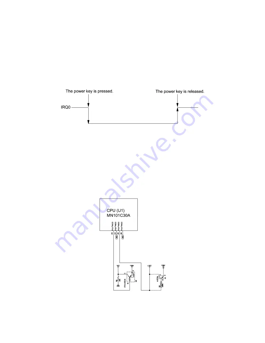
As shown in Figure 3.2-6, pressing the ON/OFF key turns the CPU's IRQ0 Low so as to
interrupt the CPU.
Releasing the ON/OFF key turns the IRQ0 High. Upon detection of the High IRQ0, the
CPU checks the P11 and P13 status. According to the status, it switches to the normal
operation mode, calendar clock mode, or LCD OFF mode.
Figure 3.2-6 ON/OFF Sequence
Switching between calendar clock mode and LCD OFF mode
Port P11 on the CPU switches Vcc that is connected to the photo-interrupter and thermal
print head. Port 13 switches LVcc that is connected to the LCD driver and its divider
resistor.
If the CPU sets P11 in high impedance to turn Vcc to 0V, then pressing the ON/OFF key
switches to the calendar clock mode.
If the CPU sets P13 to 0V to turn LVcc to 0V, then pressing the ON/OFF key switches to
the LCD OFF mode.
Figure 3.2-7 Mode Switching Circuit
Summary of Contents for P-touch BB4
Page 1: ...SERVICE MANUAL MODEL P touch BB4 ...
Page 2: ...SERVICE MANUAL MODEL P touch BB4 ...
Page 5: ...Chapter I SPECIFICATIONS ...
Page 9: ...I 3 Figure 1 1 2 Key Arrangement 1 ...
Page 10: ...I 4 Figure 1 1 2 Key Arrangement 2 ...
Page 12: ...Chapter II MECHANISMS ...
Page 42: ...Chapter III ELECTRONICS ...
Page 54: ...III 11 Figure 3 2 14 Waveforms of Control Signal and Motor Drive Current ...
Page 56: ...III 13 Figure 3 2 16 Waveforms of Dial Scanning Pulse Outputs ...
Page 57: ...Chapter IV TROUBLESHOOTING ...
Page 60: ...IV 2 4 1 3 Troubleshooting Flows 1 Tape feeding failure ...
Page 61: ...IV 3 2 Printing failure ...
Page 62: ...IV 4 3 Powering failure Nothing appears on the LCD ...
Page 63: ...IV 5 4 Abnormal LCD indication 5 No key entry possible ...


