3-29
Confidential
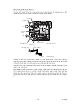
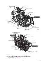
[ 4 ] Power transmission route to the head maintenance mechanism and motor
rotational direction
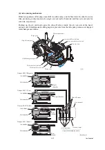
This mechanism draws its power from two motors--the ASF motor (DC motor) in the right rear
corner of the engine chassis and the paper feed motor (DC motor) on the left side. The ASF
motor is mounted in the ASF motor holder combined with the maintenance unit.
ASF motor
→
Maintenance unit (head capping and carriage lock mechanisms)
As shown on the next page, the rotational torque of the ASF motor is always transmitted via the
ASF/maintenance drive gear and idle gear 16 to the clutch gear L.
When the mode switching lever is in the left position (ASF mode), the clutch gear L also
meshes with the ASF changeover gear.
When the head/carriage unit moves to the right end of its travel, a tab on the carriage rear panel
pushes the mode switching lever to the right (purge mode). The clutch gear spring pushes the
clutch gear L to the right, away from the ASF changeover gear, to mesh with the cap lift cam
gear. This way, the ASF motor drives the head capping and carriage lock mechanisms. (See
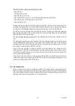
Paper feed motor
→
Maintenance unit (purge, air removing and head wiper mechanisms)
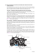
As shown on the next page, the paper feed motor drives the PF roller gear L that rotates the
paper feed roller. At the right end of the roller is the PF roller gear R that always meshes with
the clutch gear R.
When the mode switching lever is in the left position (ASF mode), the clutch gear R does not
mesh with the purge gear but it is just idling.
When the head/carriage unit moves to the right end of its travel, a tab on the carriage rear panel
pushes the mode switching lever to the right (purge mode). The clutch gear spring pushes the
clutch gear R to the right to mesh with the purge gear.
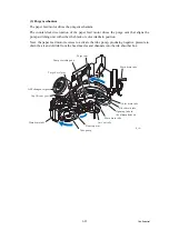
As the paper feed motor rotates counterclockwise, the planetary arm meshes with the purge cam
(as shown below), driving the purge mechanism (pump switching unit), air removing
mechanism and head wiper mechanism. On the contrary, the clockwise motor rotation causes
the planetary arm to mesh with the tube pump gear, driving the purge mechanism (tube pump).
(See
for the related components.)
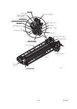
Cap lift cam switch
Tube pump
Planetary arm
Air vent tube
Main drain tube
Black drain tube
Purge cam switch
Color drain tube
Pump switching unit
Purge cam
Cap lift cam gear
ASF changeover gear
(3_20)
Opening tube to the atmospheric air
Summary of Contents for MFC-J220
Page 8: ...vi Confidential SAFETY PRECAUTIONS Symbols used in the documentation ...
Page 9: ...vii Confidential ...
Page 10: ...viii Confidential ...
Page 11: ...ix Confidential ...
Page 12: ...x Confidential ...
Page 13: ...xi Confidential ...
Page 14: ...xii Confidential ...
Page 15: ...xiii Confidential ...
Page 16: ...Confidential CHAPTER 1 PARTS NAMES AND FUNCTIONS ...
Page 20: ...1 3 Confidential 1 2 CONTROL PANEL DCP375CW ...
Page 21: ...1 4 Confidential ...
Page 22: ...1 5 Confidential DCP395CN ...
Page 23: ...1 6 Confidential ...
Page 24: ...1 7 Confidential MFC255CW 295CN ...
Page 25: ...1 8 Confidential ...
Page 26: ...1 9 Confidential MFC495CW ...
Page 27: ...1 10 Confidential ...
Page 28: ...1 11 Confidential MFC795CW ...
Page 29: ...1 12 Confidential ...
Page 30: ...1 13 Confidential DCPJ125 J315W J515W J715W 8 7 6 5 1 2 4 3 ...
Page 31: ...1 14 Confidential ...
Page 32: ...1 15 Confidential MFCJ220 J265W J270W J410 J410W J415W J615W J630W 6 7 8 5 2 4 3 1 ...
Page 33: ...1 16 Confidential Mono Start Colour Start ...
Page 34: ...1 17 Confidential DCPJ140W 6 7 8 5 2 4 3 1 ...
Page 37: ...Confidential CHAPTER 2 SPECIFICATIONS ...
Page 39: ...Confidential 2 12 PAPER 2 42 2 12 1 Paper Specifications 2 42 2 12 2 Printable Area 2 44 ...
Page 84: ...Confidential CHAPTER 3 THEORY OF OPERATION ...
Page 130: ...Confidential CHAPTER 4 ERROR INDICATION AND TROUBLESHOOTING ...
Page 135: ...4 3 Confidential For MFC only Replace Ink ...
Page 187: ...Confidential CHAPTER 5 HANDLING DATA HELD IN THE MACHINE PRIOR TO REPAIR ...
Page 191: ...Confidential CHAPTER 6 DISASSEMBLY REASSEMBLY AND LUBRICATION ...
Page 193: ...Confidential 6 2 LUBRICATION 6 103 ...
Page 302: ...Confidential CHAPTER 7 ADJUSTMENTS AND UPDATING OF SETTINGS REQUIRED AFTER PARTS REPLACEMENT ...
Page 309: ...7 5 Confidential 8 Alert warning message of WHQL appears Click Continue Anyway to proceed ...
Page 318: ...7 14 Confidential Head Positioning Test Pattern ...
Page 325: ...7 21 Confidential Vertical Alignment Check Pattern A 1 2 ...
Page 326: ...7 22 Confidential Vertical Alignment Check Pattern A 2 2 ...
Page 327: ...7 23 Confidential Vertical Alignment Check Pattern B ...
Page 331: ...7 27 Confidential Left Right and Bottom Margins Check Pattern ...
Page 342: ...7 38 Confidential ADF Copy Chart A B C D ...
Page 345: ...Confidential CHAPTER 8 CLEANING ...
Page 349: ...8 3 Confidential Maintenance unit Head wiper Head cap unit cleaning_duplex Rubycel stick ...
Page 350: ...Confidential CHAPTER 9 MAINTENANCE MODE ...
Page 359: ...9 7 Confidential Scanning Compensation Data List Models except DCPJ140W DCPJ140W ...
Page 362: ...9 10 Confidential Test Pattern ...
Page 367: ...9 15 Confidential Configuration List ...
Page 372: ...9 20 Confidential MFC255CW 295CN MFC495CW MFC795CW DCPJ125 J315W J515W J715W Key Entry Order ...
Page 373: ...9 21 Confidential DCPJ140W MFCJ220 J265W J270W J410 J410W J415W J615W J630W Key Entry Order ...
Page 397: ...9 45 Confidential Vertical Alignment Check Pattern A 1 2 ...
Page 398: ...9 46 Confidential Vertical Alignment Check Pattern A 2 2 ...
Page 399: ...9 47 Confidential Vertical Alignment Check Pattern B ...
Page 403: ...9 51 Confidential Left Right and Bottom Margins Check Pattern ...
Page 439: ...App 2 3 Confidential 8 Alert warning message of WHQL appears Click Continue Anyway to proceed ...
Page 521: ...App 5 3 Confidential DCPJ515W ...
Page 522: ...App 5 4 Confidential DCPJ715W MFCJ615W J630W ...
Page 523: ...App 5 5 Confidential DCPJ125 J315W MFCJ220 J265W J270W J410 J410W J415W ...
Page 524: ...App 5 6 Confidential DCPJ140W ...
Page 534: ...App 6 9 Confidential B Power supply PCB 200 V series ...


