


IV
- 24
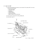
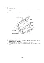
1.11 Upper Cover ASSY
(1) Disconnect the following six harnesses (seven harnesses if the battery ASSY has not been
removed) from the main PCB:
•
Cover sensor harness
•
Panel-main harness
•
CIS harness
•
Speaker harness
•
Hook switch harness
•
Scanner motor harness
•
(Battery harness if not disconnected yet)
(2) Remove screw "b" that secures the three grounding wires.
(3) Remove two screws "a."
Summary of Contents for MFC-7050C
Page 1: ...FACSIMILE EQUIPMENT SERVICE MANUAL MODEL MFC7050C ...
Page 4: ...CHAPTER I GENERAL DESCRIPTION ...
Page 10: ...CHAPTER II INSTALLATION ...
Page 11: ...CONTENTS 1 INSTALLING THE UPDATE DATA TO THE FACSIMILE EQUIPMENT II 1 ...
Page 14: ...CHAPTER III THEORY OF OPERATION ...
Page 16: ...III 1 1 OVERVIEW ...
Page 27: ...III 12 Location of Sensors and Actuators ...
Page 30: ...III 15 ...
Page 35: ...CHAPTER IV DISASSEMBLY REASSEMBLY AND LUBRICATION ...
Page 41: ...IV 4 n n Disassembly Order Flow ...
Page 93: ...IV 56 1 33 Ink Foam 1 Take up the ink foam from the lower cover ...
Page 94: ...IV 57 1 34 Harness Routing ...
Page 96: ...IV 59 2 Control panel locks 3 Scanner frame ASSY and separation roller gear ...
Page 97: ...IV 60 4 Top cover lock spring 5 Gear plate ASSY ...
Page 98: ...IV 61 6 Hinges 7 Frame chassis ASSY ...
Page 99: ...IV 62 8 Idle pulley holder 9 Maintenance ASSY ...
Page 100: ...IV 63 10 Exit roller ASSY 11 Large feed roller ASSY ...
Page 101: ...CHAPTER V MAINTENANCE MODE ...
Page 108: ...V 6 Scanning Compensation Data List ...
Page 123: ...CHAPTER VI ERROR INDICATION AND TROUBLESHOOTING ...
Page 135: ...May 99 SM8XD115 Printed in Japan ...
Page 136: ...MFC7050C Appendix 1 EEPROM Customizing Codes ...
Page 153: ...E Power Supply PCB ...


