III
- 9
(2)
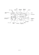
Head capping and cleaning with head wipers
Shown below are head capping and cleaning mechanisms. Upon completion of printing, the
carrier travels rightwards to the home position and moves the head cap lever of the head cap unit
to the right, bringing the head cap unit up to the position where the head caps come into tight
contact with the print heads. Capping the nozzles of the print heads this way prevents them from
drying up or becoming dirtied with dust when they are not in use. If the carrier travels to the left
for printing, the head cap unit goes down to the previous position with the springs.
The above head capping mechanism moves also the head wiper unit up. When the carrier travels
to the left, the wipers clean ink remaining on the head surfaces and then the carrier's boss presses
the wiper release lever to return the wiper unit down to the previous position.
Summary of Contents for MFC-7050C
Page 1: ...FACSIMILE EQUIPMENT SERVICE MANUAL MODEL MFC7050C ...
Page 4: ...CHAPTER I GENERAL DESCRIPTION ...
Page 10: ...CHAPTER II INSTALLATION ...
Page 11: ...CONTENTS 1 INSTALLING THE UPDATE DATA TO THE FACSIMILE EQUIPMENT II 1 ...
Page 14: ...CHAPTER III THEORY OF OPERATION ...
Page 16: ...III 1 1 OVERVIEW ...
Page 27: ...III 12 Location of Sensors and Actuators ...
Page 30: ...III 15 ...
Page 35: ...CHAPTER IV DISASSEMBLY REASSEMBLY AND LUBRICATION ...
Page 41: ...IV 4 n n Disassembly Order Flow ...
Page 93: ...IV 56 1 33 Ink Foam 1 Take up the ink foam from the lower cover ...
Page 94: ...IV 57 1 34 Harness Routing ...
Page 96: ...IV 59 2 Control panel locks 3 Scanner frame ASSY and separation roller gear ...
Page 97: ...IV 60 4 Top cover lock spring 5 Gear plate ASSY ...
Page 98: ...IV 61 6 Hinges 7 Frame chassis ASSY ...
Page 99: ...IV 62 8 Idle pulley holder 9 Maintenance ASSY ...
Page 100: ...IV 63 10 Exit roller ASSY 11 Large feed roller ASSY ...
Page 101: ...CHAPTER V MAINTENANCE MODE ...
Page 108: ...V 6 Scanning Compensation Data List ...
Page 123: ...CHAPTER VI ERROR INDICATION AND TROUBLESHOOTING ...
Page 135: ...May 99 SM8XD115 Printed in Japan ...
Page 136: ...MFC7050C Appendix 1 EEPROM Customizing Codes ...
Page 153: ...E Power Supply PCB ...


