


III
- 13
3.
CONTROL ELECTRONICS
3.1
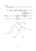
Configuration
The hardware configuration of the facsimile equipment is shown below.
Configuration of Facsimile Equipment
*1 On the main PCB is the registration sensor.
*2 On the cover sensor PCB is the cover sensor.
*3 On the hook switch PCB is the hook switch sensor.
*4 On the document sensor PCB are these sensors:
• Document front sensor (PH1)
• Document rear sensor (PH2)
*5 On the sensor FPC is the carrier home position sensor.
*6 On the ink empty sensor PCB is the ink empty sensor.
Summary of Contents for MFC-7050C
Page 1: ...FACSIMILE EQUIPMENT SERVICE MANUAL MODEL MFC7050C ...
Page 4: ...CHAPTER I GENERAL DESCRIPTION ...
Page 10: ...CHAPTER II INSTALLATION ...
Page 11: ...CONTENTS 1 INSTALLING THE UPDATE DATA TO THE FACSIMILE EQUIPMENT II 1 ...
Page 14: ...CHAPTER III THEORY OF OPERATION ...
Page 16: ...III 1 1 OVERVIEW ...
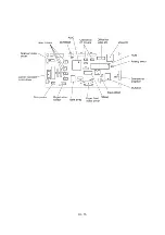
Page 27: ...III 12 Location of Sensors and Actuators ...
Page 30: ...III 15 ...
Page 35: ...CHAPTER IV DISASSEMBLY REASSEMBLY AND LUBRICATION ...
Page 41: ...IV 4 n n Disassembly Order Flow ...
Page 93: ...IV 56 1 33 Ink Foam 1 Take up the ink foam from the lower cover ...
Page 94: ...IV 57 1 34 Harness Routing ...
Page 96: ...IV 59 2 Control panel locks 3 Scanner frame ASSY and separation roller gear ...
Page 97: ...IV 60 4 Top cover lock spring 5 Gear plate ASSY ...
Page 98: ...IV 61 6 Hinges 7 Frame chassis ASSY ...
Page 99: ...IV 62 8 Idle pulley holder 9 Maintenance ASSY ...
Page 100: ...IV 63 10 Exit roller ASSY 11 Large feed roller ASSY ...
Page 101: ...CHAPTER V MAINTENANCE MODE ...
Page 108: ...V 6 Scanning Compensation Data List ...
Page 123: ...CHAPTER VI ERROR INDICATION AND TROUBLESHOOTING ...
Page 135: ...May 99 SM8XD115 Printed in Japan ...
Page 136: ...MFC7050C Appendix 1 EEPROM Customizing Codes ...
Page 153: ...E Power Supply PCB ...


