Brother DCP-L5500D Service Manual Download Page 205

3-45

Confidential

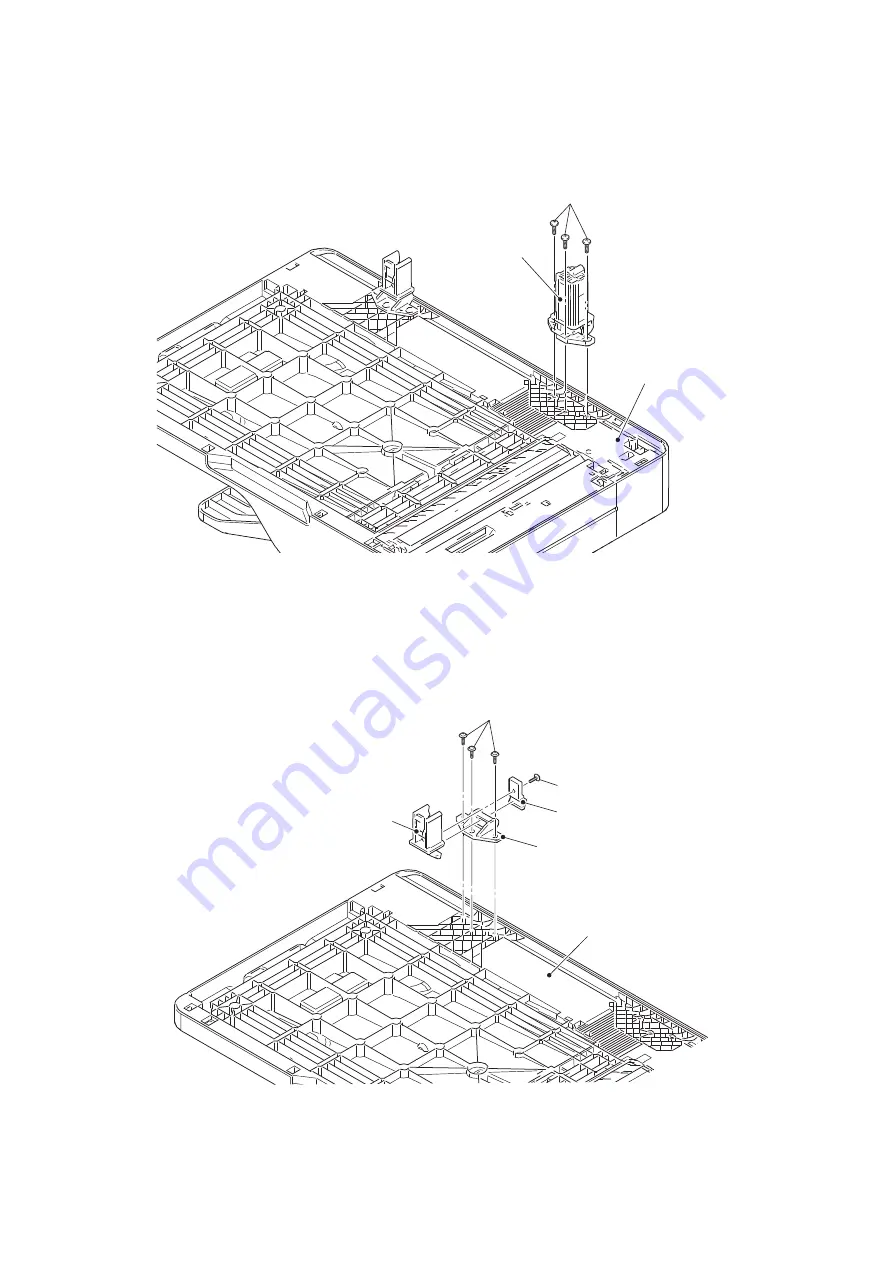
9.11.2 Hinge L ASSY, Hinge R, Hinge R support, Hinge arm R

(1) Remove the three taptite bind B M4x12 screws to remove the hinge L ASSY from the 

ADF unit.

Fig. 3-35

(2) Remove the taptite cup B M3x10 screw to remove the hinge R support and hinge R from 

the hinge arm R.

(3) Remove the three taptite cup B M3x10 screws to remove the hinge arm R from the ADF 

unit.

Fig. 3-36

Taptite bind B M4x12

Hinge L ASSY

ADF unit

Taptite cup B M3x10

Taptite cup B M3x10

Hinge R support

Hinge R

Hinge arm R

ADF unit

Summary of Contents for DCP-L5500D

Page 1: ...DW L5702DW L5750DW MFC L5755DW L5800DW L5802DW 5850DW MFC L5900DW L5902DW L6700DW L6702DW MFC L6750DW L6800DW L6900DW L6902DW Read this manual thoroughly before maintenance work Keep this manual in a convenient place for quick and easy reference at all times December 2015 SM FAX170 8C5J 1 MODEL LT Lower Tray LT 5500 5505 6500 6505 TT Tower Tray TT 4000 OPTION ...

Page 2: ...s of Wi Fi Alliance WPA WPA2 Wi Fi Protected Setup and Wi Fi Protected Setup logo are trademarks of Wi Fi Alliance Flickr and the Flickr logo are the trademarks and or registered trademarks of Yahoo Inc Android Google Cloud Print Google Drive Google Chrome Picasa Web Albums and Google Play are trademarks of Google Inc Use of these trademarks are subject to Google Permissions Mozilla and Firefox ar...

Page 3: ...KS INC ALL RIGHTS RESERVED 2008 Devicescape Software Inc All rights reserved This product includes the KASAGO TCP IP software developed by ZUKEN ELMIC Inc Other Information FlashFX is a registered trademark of Datalight Inc FlashFX Copyright 1998 2014 Datalight Inc U S Patent Office 5 860 082 6 260 156 FlashFX Pro is a trademark of Datalight Inc FlashFX Tera is a trademark of Datalight Inc Relianc...

Page 4: ...roubleshooting 2 2 2 OVERVIEW 2 4 2 1 Cross section Drawing 2 4 2 1 1 Printer part 2 4 2 1 2 Scanner part 2 5 2 2 Paper Feeding 2 6 2 2 1 Printer part 2 6 2 2 2 Scanner part 2 7 2 3 Operation of Each Part 2 8 2 4 Block Diagram 2 10 2 5 Main Components 2 11 3 ERROR INDICATIONS 2 12 3 1 Error Codes 2 12 3 2 Error Messages 2 22 3 3 Communication Errors 2 34 4 TROUBLESHOOTING 2 38 4 1 Error Cause and ...

Page 5: ... Problems 2 111 4 7 1 New toner is not detected 2 111 4 7 2 Toner cartridge cannot be recognized 2 111 4 7 3 Error message prompting toner cartridge replacement does not disappear 2 111 4 7 4 Drum error 2 112 4 7 5 Error message prompting drum replacement does not disappear 2 112 4 8 Troubleshooting for Fuser Unit Problems 2 113 4 8 1 Fuser unit failure 2 113 4 9 Troubleshooting for Laser Unit Pro...

Page 6: ... 26 9 DISASSEMBLY PROCEDURE 3 27 9 1 Preparation 3 27 9 2 Paper tray 3 28 9 3 Back cover Outer chute 3 30 9 4 Fuser cover 3 31 9 5 Fuser unit 3 32 9 6 MP cover ASSY 3 35 9 7 Front cover ASSY 3 37 9 8 Side cover L 3 38 9 9 Side cover R 3 39 9 10 ADF document scanner unit 3 40 9 11 ADF unit 3 43 9 11 1 ADF unit 3 43 9 11 2 Hinge L ASSY Hinge R Hinge R support Hinge arm R 3 45 9 11 3 ADF cover ASSY D...

Page 7: ...SY 3 91 9 27 Registration clutch T1 pickup clutch 3 92 9 28 Main frame L ASSY 3 93 9 29 Paper feed motor 3 96 9 30 Develop joint gear 37 Develop joint 3 98 9 31 Toner amount detection sensor PCB ASSY light reception 3 99 9 32 MP solenoid 3 100 9 33 Develop clutch 51R 3 101 9 34 Internal temperature sensor 3 102 9 35 Fuser drive gear 39 3 103 9 36 Eject motor 3 105 9 37 Back cover duplex tray senso...

Page 8: ...Value of Laser Unit 4 6 1 7 Acquiring White Level Data Function Code 55 4 7 1 8 Adjusting Left end and Upper end Print Position Function Code 45 TT only 4 7 1 9 Resetting to Factory Shipping State 4 7 2 IF YOU REPLACE THE LOW VOLTAGE POWER SUPPLY PCB ASSY 4 8 2 1 Resetting Irregular Power Supply Counter of the Low voltage Power Supply PCB Function Code 88 4 8 3 IF YOU REPLACE THE LASER UNIT 4 9 3 ...

Page 9: ...ion function code 32 5 16 1 3 11 Display LAN connection status function code 33 5 20 1 3 12 Set PC print functions function code 43 5 21 1 3 13 Change USB No return value Adjust left end print position Adjust upper end print position Set HEXDUMP Mode function code 45 5 24 1 3 14 Adjust printable range for each speed level Full speed Half speed for thick paper Quiet Mode function code 46 5 27 1 3 1...

Page 10: ...Communication Error List 5 61 2 2 Reset the Drum Unit Counter 5 61 CHAPTER 6 WIRING DIAGRAM 1 WIRING DIAGRAM 6 1 CHAPTER 7 PERIODICAL MAINTENANCE 1 SAFETY PRECAUTIONS 7 1 2 PERIODICAL REPLACEMENT PARTS 7 2 2 1 Preparation 7 2 2 2 Fuser unit 7 3 2 3 Laser unit 7 7 2 4 PF kit MP 7 17 2 5 PF kit 1 7 18 2 6 PF kit 2 3 4 5 7 20 APPENDIX 1 SERIAL NUMBERING SYSTEM APPENDIX 2 DELETING USER SETTING INFORMA...

Page 11: ...r moderate injuries IMPORTANT IMPORTANT indicates a potentially hazardous situation which if not avoided may result in damage to property or loss of product functionality Prohibition icons indicate actions that must not be performed Electrical Hazard icons alert you to possible electrical shocks Fire hazard icons alert you to the possibility of a fire Hot Surface icons warn you not to touch produc...

Page 12: ...s well as any telephone RJ 11 MFC only or Ethernet RJ 45 cables Network models only from the product Never push objects of any kind into this product through cabinet slots since they may touch dangerous voltage points or short out parts Unplug the power plug regularly to clean it Use a dry cloth to clean the root of the plug blades and between the blades If the power plug is plugged into the outle...

Page 13: ...uring an electrical storm MFC only Use caution when installing or modifying telephone lines Never touch telephone wires or terminals that are not insulated unless the telephone line has been unplugged from the wall jack Never install telephone wiring during a lightning storm Never install a telephone wall jack in a location that is wet or may become wet for example near a refrigerator or other app...

Page 14: ...duct it may cause a fire or electric shock Metal object such as a clip or a staple Precious metal such as a necklace or a ring Container holding water or liquid such as a glass a flower vase or a flower pot HOT SURFACE After you have just used the product some internal parts of the product will be extremely hot Wait at least 10 minutes for the product to cool down before you touch the internal par...

Page 15: ...ne equipment basic safety precautions should always be followed to reduce the risk of fire electrical shock and injury to people These important safety precautions include the following 1 DO NOT use this product near water or locations that may become wet for example near a bath tub wash bowl kitchen sink or washing machine in a wet basement or near a swimming pool 2 Avoid using this product durin...

Page 16: ...tial IMPORTANT DO NOT remove or damage any of the caution or warning labels inside the product DO NOT put objects on top of the product Doing so could increase the risk of overheating should the product malfunction ...

Page 17: ...le von Störungen der Lasereinheit muß diese ersetzt werden Das Gehäuse der Lasereinheit darf nicht geöffnet werden da sonst Laserstrahlen austreten können Additional Information When servicing the optical system of the machine be careful not to place a screwdriver or other reflective object in the path of the laser beam Be sure to take off any personal accessories such as watches and rings before ...

Page 18: ... of indebtedness Certificates of Deposit Armed forces service or draft papers Passports Postage stamps cancelled or uncancelled Food stamps Immigration Papers Welfare documents Checks or drafts drawn by governmental agencies Identifying badges or insignias In addition driving licenses and or Certificates of Title to motor vehicles may not be copied under certain national laws Copyrighted works can...

Page 19: ...eless LAN N A Wired Wired Wireless Duplex Printing Auto Duplex Copy N A Duplex Scan N A Scanning Method CIS Dual CIS LCD Type 3 7 TFT ColorLCD 9 3 cm 93 4 mm 4 85 TFT ColorLCD 12 3 cm 123 2 mm FAX N A FB A4 LTR LGL USB Host front USB Host rear N A NFC N A PCL PS N A Paper Input Standard Tray 250 sheets 520 sheets Lower Tray Option 250 sheets LT 5500 or 520 sheets LT 6500 x 2 pcs Max 1 040 sheets T...

Page 20: ... Scan N A N A Scanning Method CIS Dual CIS CIS Dual CIS LCD Type 3 7 TFT ColorLCD 9 3 cm 93 4 mm 4 85 TFT ColorLCD 12 3 cm 123 2 mm FAX FB A4 LTR USB Host front USB Host rear N A NFC N A N A PCL PS Paper Input Standard Tray 250 sheets Lower Tray Option 250 sheets LT 5500 or 520 sheets LT 6500 x 2 pcs Max 1 040 sheets Tower Tray Option N A Specifications are subject to change without notice ...

Page 21: ...9 3 cm 93 4 mm 4 85 TFT ColorLCD 12 3 cm 123 2 mm FAX FB A4 LTR LGL USB Host front USB Host rear N A NFC N A PCL PS Paper Input Standard Tray 250 sheets 520 sheets Lower Tray Option 250 sheets LT 5500 or 520 sheets LT 6500 x 2 pcs Max 1 040 sheets 250 sheets LT 5500 for the U S A LT 5505 for Europe or 520 sheets LT 6500 for the U S A LT 6505 for Europe x 2 pcs Max 1 040 sheets 250 sheets LT 5505 o...

Page 22: ...rtex A9 800 MHz Backup clock Up to 60 hours Dimensions W x D x H Carton size 545 x 520 x 641 mm 21 5 x 20 5 x 25 2 inch 599 x 526 x 629 mm 23 6 x 20 7 x 24 8 inch 599 x 526 x 659 mm 23 6 x 20 7 x 25 9 inch Machine size 435 x 427 x 486 mm 17 1 x 16 8 x 19 1 inch 495 x 427 x 486 mm 19 5 x 16 8 x 19 1 inch 495 x 427 x 518 mm 19 5 x 16 8 x 20 4 inch Weights with carton 20 2 kg 44 5 lb 19 7 kg 43 4 lb ...

Page 23: ...ode Up to 25 26 ppm CPU Cortex A9 800 MHz Backup clock Up to 60 hours Dimensions W x D x H Carton size 585 x 556 x 651 mm 23 0 x 21 9 x 25 6 inch 545 x 520 x 641 mm 21 5 x 20 5 x 25 2 inch Machine size 435 x 427 x 486 mm 17 1 x 16 8 x 19 1 inch Weights with carton 20 3 kg 44 7 lb 20 1 kg 44 2 lb for Europe 20 3 kg 44 7 lb for Asia 19 8 kg 43 6 lb except for Brazil 19 7 kg 43 5 lb for Brazil 20 2 k...

Page 24: ...etter Up to 40 42 ppm Quiet Mode Up to 25 26 ppm Up to 46 48 ppm Quiet Mode Up to 25 26 ppm except for Asia Up to 50 52 ppm Quiet Mode Up to 25 26 ppm for Asia Up to 46 48 ppm Quiet Mode Up to 25 26 ppm CPU Cortex A9 800 MHz Backup clock Up to 60 hours Dimensions W x D x H Carton size 599 x 526 x 629 mm 23 6 x 20 7 x 24 8 inch 599 x 526 x 659 mm 23 6 x 20 7 x 25 9 inch Machine size 495 x 427 x 486...

Page 25: ...h except for Italy CONSIP 599 x 526 x 762 mm 23 6 x 20 7 x 30 0 inch for Italy CONSIP 599 x 526 x 762 mm 23 6 x 20 7 x 30 0 inch except for Oceania 599 x 526 x 659 mm 23 6 x 20 7 x 25 9 inch for Oceania Machine size 495 x 427 x 518 mm 19 5 x 16 8 x 20 4 inch Weights with carton 23 3 kg 51 4 lb 22 6 kg 49 8 lb for the U S A 22 9 kg 50 4 lb for Europe except Italy CONSIP 23 5 kg 51 8 lb for Italy CO...

Page 26: ...mm of its whole size is the boss parts which connects with the machine 363 x 384 x 152 mm 14 3 x 15 1 x 6 0 inch The height 20 mm of its whole size is the boss parts which connects with the machine 660 x 660 x 717 4 mm 26 0 x 26 0 x 28 2 inch Weights 2 8 kg 6 2 lb 3 9 kg 8 5 lb 46 6 kg 102 7 lb 47 7 kg 105 2 lb with AC cord Specifications are subject to change without notice ...

Page 27: ... Network node type N A NC 8500w Model MFC 8530DN MFC 8535DN MFC 8540DN MFC L5700DN MFC L5700DW MFC L5702DW MFC L5750DW MFC L5755DW MFC L5800DW MFC L5802DW MFC L5850DW MFC L5900DW MFC L5902DW MFC L6700DW MFC L6702DW MFC L6750DW MFC L6800DW MFC L6900DW MFC L6903DW Wired network Network node type NC 8900h Wireless network Network node type N A NC 8500w Specifications are subject to change without not...

Page 28: ...ce parts Fuser unit Up to 200 000 pages Laser unit Up to 200 000 pages PF kit 1 Up to 100 000 pages Up to 200 000 pages PF kit 2 Up to 200 000 pages PF kit 3 Up to 200 000 pages PF kit 4 Up to 200 000 pages PF kit 5 Up to 200 000 pages PF kit MP Up to 50 000 pages Specifications are subject to change without notice As for replacement of the periodical maintenance parts refer to PERIODICAL MAINTENA...

Page 29: ...100 000 pages Up to 125 000 pages Up to 150 000 pages Periodical maintenance parts Fuser unit Up to 200 000 pages Laser unit Up to 200 000 pages PF kit 1 Up to 100 000 pages Up to 200 000 pages PF kit 2 Up to 200 000 pages PF kit 3 Up to 200 000 pages PF kit 4 Up to 200 000 pages PF kit 5 Up to 200 000 pages PF kit MP Up to 50 000 pages Specifications are subject to change without notice As for re...

Page 30: ...ccordance with ISO IEC 19752 Shelf life 2 years without opening 6 months after opening Drum unit Life expectancy Approximately 30 000 pages 1 page job Approximately 50 000 pages 3 page job The life expectancy varies according to the use condition Shelf life 2 years The shelf life of toner cartridge and drum unit is guaranteed under the normal condition as below Temperature Normal condition 0 to 40...

Page 31: ...ife 2 years without opening 6 months after opening Drum unit Life expectancy Approximately 30 000 pages 1 page job Approximately 50 000 pages 3 page job The life expectancy varies according to the use condition Shelf life 2 years The shelf life of toner cartridge and drum unit is guaranteed under the normal condition as below Temperature Normal condition 0 to 40 C Humidity Normal condition 35 RH t...

Page 32: ...ard Toner Approx 3 000 pages High Capacity Toner Approx 8 000 pages Super High Capacity Toner Approx 12 000 pages Approx 12 000 pages for Asia MFC L5702DW N A except for Asia MFC L5702DW Approx 12 000 pages except for the U S A N A for the U S A Approx 12 000 pages Ultra High Capacity Toner N A Approx 20 000 pages When printing A4 Letter size one sided pages in accordance with ISO IEC 19798 Self l...

Page 33: ...change without notice Model MFC 8530DN MFC 8535DN MFC 8540DN MFC L5700DN MFC L5700DW MFC L5702DW MFC L5750DW MFC L5755DW MFC L5800DW MFC L5802DW MFC L5850DW MFC L5900DW MFC L5902DW MFC L6700DW MFC L6702DW MFC L6750DW MFC L6800DW MFC L6900DW MFC L6902DW Modem speed 33 600 bps Fax Transmission speed Approximately 2 5 sec ITU T Test Chart Std resolution JBIG ITU T group Super G3 Color FAX Sending Rec...

Page 34: ...MFC 8530DN MFC 8535DN MFC L5700DN MFC L5702DW MFC L5800DW MFC L5802DW MFC 8540DN MFC L5750DW MFC L5755DW MFC L5850DW MFC L5900DW MFC L5902DW MFC L6700DW MFC L6702DW MFC L6750DW MFC L6800DW MFC L6900DW MFC L6902DW Copy speed A4 Letter Up to 40 42 cpm Up to 46 48 cpm except for Asia Up to 50 52 cpm for Asia Up to 50 52 cpm First copy out time From Ready mode and Paper tray Less than 9 2 secs Less th...

Page 35: ...e N A 56 34 100 34 Model MFC 8530DN MFC 8535DN MFC L5700DN MFC L5702DW MFC 8540DN MFC L5750DW MFC L5755DW MFC L5800DW MFC L5802DW MFC L5850DW MFC L5900DW MFC L5902DW MFC L6700DW MFC L6702DW MFC L6750DW MFC L6800DW MFC L6900DW MFC L6902DW Resolution Optical FB Max 1 200 x 1 200 dpi ADF Max 600 x 600 dpi Resolution Interpolated Max 19 200 x 19 200 dpi Scanning speed Mono Color in accordance with ISO...

Page 36: ...damage electronic parts Before handling the PCBs touch a metal section of the machine to discharge static electricity When transporting PCBs be sure to wrap them in conductive sheets When replacing the PCBs wear a grounding wrist band and perform replacement on an antistatic mat Also take care not to touch the conductor sections on the flat cables 4 Be sure to always observe all warnings 5 After r...

Page 37: ...e heat moisture or dust 4 Hold the machine level while moving it Be sure to move or lift the machine with 2 or more people Fig 2 1 Power supply 1 Power described on the rating label attached on the machine is supplied Power fluctuation should be within 10 of the rated voltage 2 The AC input power supply is within the regulated value 3 The cables and harnesses are connected correctly 4 The fuses ar...

Page 38: ...tion pad may cause paper feed problems If condensation has formed in the machine leave the machine for at least two hours until it reaches room temperature If the drum unit is unpacked soon after it is moved to a warm room from a cold location condensation may occur inside the unit which may cause printing failure Leave the drum unit for one or two hours until it reaches room temperature and then ...

Page 39: ...LT or TT separation pad T4 LT or TT paper pick up roller T4 LT or TT paper empty actuator T3 LT or TT paper dust cleaning roller T3 LT or TT paper feed actuator T3 LT or TT separation roller T3 LT or TT separation pad T3 LT or TT paper pick up roller T3 LT or TT paper empty actuator T2 LT or TT paper dust cleaning roller T2 LT or TT paper feed actuator T2 LT or TT separation roller T2 LT or TT sep...

Page 40: ...Second side document hold Second side CIS unit Scanner glass strip First side CIS glass Scanner glass strip Second side CIS glass Document separate roller Document separate roller ASSY ADF cover sensor Document guide Document tray Document cover Document stopper Scanner glass Document eject roller Document pinch roller First side document hold First side CIS unit Document detection sensor PCB Docu...

Page 41: ... Paper Feeding 2 2 1 Printer part Fig 2 4 Back side Eject to back side Duplex path Front side Paper tray 1 path Paper tray 2 path Paper tray 3 path Paper tray 4 path Paper tray 5 path Feed from MP tray Eject to output tray ...

Page 42: ...2 7 Confidential 2 2 2 Scanner part Common to Legal A4 models Fig 2 5 Document feed path ...

Page 43: ...the feeding path Registration rear actuator Registration rear sensor Detects paper pass and adjusts the writing start position for the paper Detects paper jams in the front or center section of the machine Detects the rear edge of the paper to determine the paper size Heat film Pressure roller Fuses the toner transferred to paper by heat and pressure and feeds paper to the eject roller 1 Eject act...

Page 44: ... with USB host on the rear side only Document pick up roller Feeds document from the document tray Document separate roller ADF separation pad Separates the document fed from the document tray into single sheets Document detection actuator Document detection sensor Detects whether a document is set in the ADF Document scanning position actuator Document scanning position sensor Detects the documen...

Page 45: ...only Paper empty sensor PCB Toner amount detection sensor PCB light reception Low voltage power supply PCB T2TT pickup clutch T2TT jam sensor PCB T2TT paper empty sensor PCB T2TT paper feed sensor PCB T3TT pickup clutch T3TT release clutch T3TT jam sensor PCB T4TT pickup clutch T4TT release clutch T4TT jam sensor PCB T4TT paper empty sensor PCB T4TT paper feed sensor PCB T5TT pickup clutch T5TT re...

Page 46: ...h 51R Duplex tray Paper stopper Front cover ASSY MP cover ASSY High voltage power supply PCB ASSY PF roller holder ASSY MP roller holder ASSY T1 pickup clutch LT TT connector Paper tray Paper feed motor Registration clutch Back cover duplex tray sensor Internal temperature sensor Low voltage power supply PCB ASSY Main PCB ASSY T1 paper feed sensor PCB ASSY MP paper empty sensor PCB ASSY Paper empt...

Page 47: ...ture rise when the heater was ON 2 40 0203 Eject motor failure was detected 2 38 050A The hardware detected a temperature error through the center thermistor or the side thermistor of the fuser unit 2 41 0300 Cannot detect the lock signal of the polygon motor for the laser unit second time 2 39 050B When the center thermistor of the fuser unit was lower than the idle temperature the side thermisto...

Page 48: ... failure 2 43 2402 1801 A communication error occurred between the ASIC and T2LT control PCB in the engine LT only 2 43 2403 1802 A communication error occurred between the ASIC and T3LT control PCB ASSY in the engine LT only 2 43 2404 1803 2405 1808 A communication error occurred between the ASIC and TT control PCB in the engine 2 43 2408 1901 Detected a TT motor failure 2 44 2409 1A01 2501 1B01 ...

Page 49: ... 2E04 4004 2E05 4200 The number of rotations of the drum unit has reached the upper limit Printing does not stop 2 44 2E06 4201 2E07 4202 2E08 4203 2E0A 4204 2F01 4300 2F02 4400 2F03 4500 The number of printable pages of the fuser unit has reached the upper limit 2 45 2F04 4600 The number of printable pages of the laser unit has reached the upper limit 2 45 2F05 4700 2F06 4800 2F07 4900 2F08 4A00 ...

Page 50: ...t 1 have reached the upper limit 2 46 6103 5003 Printable pages set for PF kit 2 have reached the upper limit 2 46 6104 5004 Printable pages set for PF kit 3 have reached the upper limit 2 46 6200 Detected that the drum unit was not set by detecting the GRID terminal current 2 48 5005 Printable pages set for PF kit 4 have reached the upper limit 2 46 6201 5006 Printable pages set for PF kit 5 have...

Page 51: ...t detect paper pass within the specified time after the T1 paper feed sensor detected paper pass 2 53 6E00 7400 6F00 Detected irregular power supply for less than 100 times 2 50 7401 When printing from the paper tray 2 the T2 LT or TT paper feed sensor does not detect paper pass within the specified time while the T2 LT or TT paper empty sensor detects some paper set 2 54 7000 The eject sensor doe...

Page 52: ...1 paper feed sensor detected open paper tray 1 before registering printing data to engine 2 63 7A01 8502 When printing from paper tray 2 to 5 the T2 LT or TT paper feed sensor detected open paper tray 2 before registering printing data to engine 2 63 7A02 8503 When printing from paper tray 3 to 5 the T3 LT or TT paper feed sensor detected open paper tray 3 before registering printing data to engin...

Page 53: ... over 10 mm shorter than letter size during receiving fax data or printing a list or report 2 66 870B 8F01 870C 8F02 870D 8F03 870E 9001 When printing from the MP tray the size of paper set in the MP tray does not match the size specified by the driver 2 67 870F 9002 When printing from the paper tray 1 the size of paper set in the paper tray 1 does not match the size specified by the driver 2 67 8...

Page 54: ...nting from paper tray 2 a paper size not supported for paper tray 2 was specified from the driver 2 72 9302 When printing from paper tray 1 the T1 paper empty sensor or the T1 paper feed sensor detected that there was no paper set in paper tray 1 2 69 9704 When printing from paper tray 3 a paper size not supported for paper tray 3 was specified from the driver 2 72 9303 When printing from paper tr...

Page 55: ...d side CIS was not within the correct range second time 2 77 A000 Image processing was not completed correctly because the number of pixels required for image processing is insufficient in the scanned second side data 2 73 BD00 A black level not within the standard was scanned when function code 55 was executed 2 77 A200 The document scanning position sensor detected that the document length was 9...

Page 56: ...ROM 2 80 CA00 E702 Read error in the flash ROM 2 80 D100 An error occurred while initializing the modem 2 79 E900 An error occurred while initializing the NFC 2 80 D200 Detected that the modem PCB is not connected 2 79 EC00 A USB device not within the specification is connected to the USB terminal resulting in over current 2 81 D800 An error occurred while initializing the touch panel 2 79 ED00 Fa...

Page 57: ...he document passing even after the document has been fed for the specified time A300 2 73 Drum Slide the Green tab on Drum Unit Detected discharge that may be attributable to dirty corona wire on the drum unit 6A00 2 50 Firmware Update You must update the firmware Firmware version of the main PCB is older than that of the TT and LT 9400 2 71 Ignore Data Press Stop Detected undecodable data during ...

Page 58: ... pass 7402 2 55 Jam Tray3 Remove the jammed paper from Tray 3 When printing from the paper tray 3 the registration front sensor or the T2 T3TT jam sensor does not detect paper pass within the specified time after the T3 LT or TT paper feed sensor detected paper pass 7502 2 57 Jam Tray4 Remove the jammed paper from Tray 4 When printing from the paper tray 4 the registration front sensor or the T2 T...

Page 59: ...ired C004 2 78 Machine Error Detected that the modem PCB is not connected D200 2 79 Machine Error A machine error occurred Refer to error code Maintenance Replace Fuser The number of printable pages of the fuser unit has reached the upper limit 4500 2 45 Replace Laser The number of printable pages of the laser unit has reached the upper limit 4600 2 45 Replace PF Kit MP Printable pages set for PF ...

Page 60: ...n press Retry When printing from the paper tray 3 paper type setting in the machine does not match the setting in the driver 9204 2 68 Reload correct paper in Tray4 then press Retry When printing from the paper tray 4 paper type setting in the machine does not match the setting in the driver 9205 2 68 Reload correct paper in Tray5 then press Retry When printing from the paper tray 5 paper type set...

Page 61: ...d paper in Tray 1 then press Retry When printing from the paper tray 1 the T1 paper feed sensor does not detect paper pass within the specified time while the T1 paper empty sensor detects some paper set 7301 2 53 No Paper Fed T2 Reload paper in Tray 2 then press Retry When printing from the paper tray 2 the T2 LT or TT paper feed sensor does not detect paper pass within the specified time while t...

Page 62: ... paper set in paper tray 1 At Fax List printing 4 2 1 When printing from paper tray 1 the T1 paper empty sensor or the T1 paper feed sensor detected that there was no paper set in paper tray 1 9302 2 69 No Paper T2 Reload paper in Tray 2 When printing from paper tray 2 the T2 LT or TT paper empty sensor detected that there was no paper set in paper tray 2 At Fax List printing 4 2 1 When printing f...

Page 63: ...or detected that the toner cartridge was not set 6101 2 47 No Tray Attachment Please install the Tower Tray Attachment Brackets When the TT was connected TT balance sensor L R wasn t connected properly 1F00 2 44 No Tray T1 Reinstall Tray When printing from paper tray 1 to 5 the T1 paper feed sensor detected open paper tray 1 before registering printing data to engine 8501 2 63 When printing from p...

Page 64: ...rint data C700 2 79 Output Tray Full Remove the paper from the Standard Output Tray Machine stack sensor detected the eject paper full state at the start of printing when the machine output tray was selected as the output tray 8702 2 64 Paper Low Paper Low T1 Tray1 paper level is low 4 14 4 Paper Low T2 Tray2 paper level is low 4 14 4 Paper Low T3 Tray3 paper level is low 4 14 4 Paper Low T4 Tray4...

Page 65: ...Press Stop x The first side document scanning position sensor detected that the document length was 400 mm or longer and could not be fed to ADF double side restoration BF00 2 78 Remove the original document Turn the power off then on again Image processing was not completed correctly because the number of pixels required for image processing is insufficient in the scanned second side data A000 2 ...

Page 66: ...the correct paper size for Tray2 When printing from paper tray 2 a paper size not supported for paper tray 2 was specified from the driver 9703 2 72 Specify the correct paper size for Tray3 When printing from paper tray 3 a paper size not supported for paper tray 3 was specified from the driver 9704 2 72 Specify the correct paper size for Tray4 When printing from paper tray 4 a paper size not supp...

Page 67: ... 9004 2 67 Reload correct paper in Tray4 then press Retry When printing from the paper tray 4 the size of paper set in the paper tray 4 does not match the size specified by the driver 9005 2 67 Reload correct paper in Tray5 then press Retry When printing from the paper tray 5 the size of paper set in the paper tray 5 does not match the size specified by the driver 9006 2 67 Supplies Toner Low Dot ...

Page 68: ...f paper set in the paper tray 3 does not match the size specified by the driver 4 14 1 Wrong Paper Size T4 Reload correct paper in Tray 4 or press Retry When printing from the paper tray 4 the size of paper set in the paper tray 4 does not match the size specified by the driver 4 14 1 Wrong Paper Size T5 Reload correct paper in Tray 5 or press Retry When printing from the paper tray 5 the size of ...

Page 69: ...on 2 123 17 01 Called using a dial number that cannot be used for the NGN line 33 digits or longer or non numeric characters 2 123 17 07 No response from the caller in receiving 2 123 1C 01 Detected that access to the NGN line was not authorized T38 403 Forbidden 2 123 1C 02 No file or folder directory found as a result of search via the NGN line T38 404 Not Found 2 123 1C 03 Remote station does n...

Page 70: ...38 2 123 32 01 Remote terminal only with V 29 capability in 2 400 or 4 800 bps transmission 2 123 32 02 Remote terminal not ready for polling 2 123 32 10 Remote terminal not equipped with password function or its password switch is OFF 2 123 32 11 Remote terminal not equipped with or not ready for confidential mailbox function 2 123 32 12 Remote terminal not equipped with or not ready for relay br...

Page 71: ...n capability changed after compensation of background color 2 123 63 01 Password last 4 digits of telephone number does not match 2 123 63 02 Password not correct 2 123 63 03 Polling ID not correct 2 123 63 04 Specified confidential ID and MailBox ID do not match 2 123 63 05 Relay broad casting ID not correct 2 123 63 06 Specified Retrieval ID and MailBox Retrieval ID do not match 2 123 63 07 Sele...

Page 72: ...o call reservation 2 123 B0 04 PC interface error 2 123 C0 01 No common modulation mode or failed to poll 2 123 C0 02 Unable to detect JM 2 123 C0 03 Unable to detect CM 2 123 C0 04 Unable to detect CJ 2 123 C0 10 Cannot finish V 34 negotiation or training 2 123 C0 11 Modem error detected during V 34 negotiation or training 2 123 C0 20 Modem error detected while sending commands 2 123 C0 21 Modem ...

Page 73: ...Step Cause Remedy 1 Connection failure of the paper feed motor harness Reconnect the paper feed motor harness 2 Damaged fuser gear Replace the fuser gear 3 Paper feed motor failure Replace the paper feed motor 4 Damaged fuser unit Replace the fuser unit 5 Low voltage power supply PCB failure Replace the low voltage power supply PCB ASSY 6 Damaged part in drive sub ASSY Replace the main frame L ASS...

Page 74: ...ct the synchronized signal of the polygon motor for the laser unit second time Error code 0405 Cannot detect the synchronized signal of the polygon motor for the laser unit first time Step Cause Remedy 1 Connection failure of the laser unit flat cable Reconnect the laser unit flat cable 2 Laser unit flat cable failure Replace the laser unit flat cable 3 Laser unit failure Replace the laser unit 4 ...

Page 75: ...temperature fall greater than the specified value within the specified time Error code 0508 The side thermistor of the fuser unit did not detect a temperature rise when the heater was ON User Check Turn OFF the power switch After several seconds turn ON the power again and check that this error is reset Step Cause Remedy 1 Connection failure of the center or side thermistor harness of the fuser un...

Page 76: ... Connection failure of the center or side thermistor harness of the fuser unit Reconnect the center or side thermistor harness of the fuser unit 2 Connection failure of the fuser unit heater harness Reconnect the fuser unit heater harness 3 Connection failure of the eject sensor harness Reconnect the eject sensor harness 4 Connection failure of the low voltage power supply harness Reconnect the lo...

Page 77: ...ltage supplied to the machine In this case if the same power supply is used the same error may occur even when the low voltage power supply PCB ASSY is replaced Ask the user to review the installation environment Do not reset the power supply PCB counter before replacing it with a new one It may cause fire Step Cause Remedy 1 Connection failure of the main fan harness Reconnect the main fan harnes...

Page 78: ...the LT TT connector of the machine side or TT side 4 TT fan failure Replace the TT fan 5 TT control PCB failure Replace the TT control PCB 6 Main PCB failure Replace the main PCB ASSY Step Cause Remedy 1 Malfunction of the LT control PCB Install the latest main firmware 2 An LT TT connector failure machine side or LT side Replace the appropriate LT TT connector of the machine side or LT side 3 An ...

Page 79: ...l PCB 6 Main PCB failure Replace the main PCB ASSY Step Cause Remedy 1 Connection failure of the TT balance sensor L R harness Reconnect the TT balance sensor L R harness or relay connector harness 2 TT balance sensor L R attachment failure Reattach the TT balance sensor L R 3 LT TT connector failure machine side or TT side Replace the LT TT connector of the machine side or TT side 4 TT balance se...

Page 80: ... Chapter 5 to reset the fuser unit counter after the replacement 2 Replace the fuser unit with a new one and reset the fuser unit counter If the error display is not cleared the main PCB is faulty Replace the main PCB ASSY Step Cause Remedy 1 End of life of the laser unit Replace the laser unit Refer to 1 3 31 Reset counters for consumable parts function code 88 in Chapter 5 to reset the laser uni...

Page 81: ...f the relay front harness Reconnect the relay front harness 2 New toner actuator coming off or caught in some sections of the machine Reattach the new toner actuator 3 Develop joint coming off or caught in some sections of the machine Reattach the develop joint 4 New toner sensor failure Replace the relay front PCB ASSY 5 Paper feed drive gears failure Replace the main frame L ASSY 6 If the error ...

Page 82: ...ailure Replace the relay front PCB ASSY 6 Relay front PCB failure Replace the relay front PCB ASSY 7 Main PCB failure Replace the main PCB ASSY User Check Close the fuser cover Step Cause Remedy 1 Eject actuator coming off or caught in some sections of the machine Reattach the eject actuator 2 Fuser cover attachment failure Reattach the fuser cover 3 Connection failure of the eject sensor harness ...

Page 83: ...e Remedy 1 Dirt on the GRID terminals of the drum unit and those of the machine Clean the CHG and GRID terminals of the drum unit and those of the machine Refer to Fig 2 8 and Fig 2 9 2 Dirt on the high voltage power supply PCB terminal Clean the high voltage power supply PCB terminal 3 high voltage power supply PCB failure Replace the high voltage power supply PCB ASSY 4 Main PCB failure Replace ...

Page 84: ...emperature sensor harness 2 Internal temperature sensor failure Replace the main frame L ASSY 3 Fuser unit side thermistor failure Replace the fuser unit 4 Main PCB failure Replace the main PCB ASSY Step Cause Remedy 1 Connection failure of a fuser unit harness Reconnect the fuser unit harness 2 Connection failure of the eject sensor harness Reconnect the eject sensor harness 3 Eject sensor PCB fa...

Page 85: ...ttachment failure Check if each electrode comes back smoothly after pressing it If not reattach each electrode 3 High voltage power supply PCB failure Replace the high voltage power supply PCB ASSY 4 Main PCB failure Replace the main PCB ASSY User Check Reduce LTs to acceptable numbers Reconnect LTs Step Cause Remedy 1 Dust around the LT TT connector Clean the LT TT connector 2 Malfunction of the ...

Page 86: ...ace the eject sensor PCB ASSY 6 high voltage power supply PCB failure Replace the high voltage power supply PCB ASSY 7 Fuser unit failure Replace the fuser unit 8 Damaged fuser gears or drum gears Replace the main frame L ASSY 9 Main PCB failure Replace the main PCB ASSY User Check Remove the jammed paper Check if the back cover is open during duplex printing Step Cause Remedy 1 Foreign object in ...

Page 87: ...e machine Reattach the registration rear actuator 3 Connection failure of the registration front rear sensor harness Reconnect the registration front rear sensor harness 4 Connection failure of the registration clutch harness Reconnect the registration clutch harness 5 MP feed frame attachment failure Reattach the MP feed frame 6 Registration rear sensor failure Replace the registration front rear...

Page 88: ...econnect the HVPS flat cable 7 PF kit 1 failure Replace the PF kit 1 8 T1 pickup clutch failure Replace the T1 pickup clutch 9 T1 paper feed sensor PCB failure Replace the T1 paper feed sensor PCB ASSY 10 T1 paper empty sensor PCB failure Replace the T1 paper empty sensor PCB ASSY 11 Damaged gears in the paper feeding system Replace the main frame L ASSY 12 High voltage power supply PCB failure Re...

Page 89: ...nt failure Reattach the T2 LT or TT paper feed actuator 5 Connection failure of the T2 LT or TT pickup clutch harness Reconnect the T2 LT or TT pickup clutch harness 6 Connection failure of the T2 LT or TT paper feed sensor harness Reconnect the T2 LT or TT paper feed sensor harness 7 PF kit 2 failure Replace the PF kit 2 8 T2 LT or TT pickup clutch failure Replace the T2 LT or TT pickup clutch 9 ...

Page 90: ... the T2TT jam sensor harness 6 Connection failure of the TT control PCB harness Reconnect the TT control PCB harness 7 Connection failure of the T2LT control PCB harness Reconnect the T2LT control PCB harness 8 Connection failure of the T2LT release clutch harness Reconnect the T2LT release clutch harness 9 T2LT release clutch failure Replace the T2LT release clutch 10 Registration front rear sens...

Page 91: ...nt failure Reattach the T3 LT or TT paper feed actuator 5 Connection failure of the T3 LT or TT pickup clutch harness Reconnect the T3 LT or TT pickup clutch harness 6 Connection failure of the T3 LT or TT paper feed sensor harness Reconnect the T3 LT or TT paper feed sensor harness 7 PF kit 3 failure Replace the PF kit 3 8 T3 LT or TT pickup clutch failure Replace the T3 LT or TT pickup clutch 9 ...

Page 92: ...t the TT control PCB harness 7 Connection failure of the T2 T3LT control PCB harness Reconnect the T2 T3LT control PCB harness 8 Connection failure of the T2 T3LT release clutch harness Reconnect the T2 T3LT release clutch harness 9 Connection failure of the T3TT release clutch harness Reconnect the T3TT release clutch harness 10 T2 T3LT release clutch failure Replace the T2 T3LT release clutch 11...

Page 93: ...nt failure Reattach the T4 LT or TT paper feed actuator 5 Connection failure of the T4 LT or TT pickup clutch harness Reconnect the T4 LT or TT pickup clutch harness 6 Connection failure of the T4 LT or TT paper feed sensor harness Reconnect the T4 LT or TT paper feed sensor harness 7 PF kit 4 failure Replace the PF kit 4 8 T4 LT or TT pickup clutch failure Replace the T4 LT or TT pickup clutch 9 ...

Page 94: ...ntrol PCB harness 7 Connection failure of the T2 T3 T4LT control PCB harness Reconnect the T2 T3 T4LT control PCB harness 8 Connection failure of the T2 T3 T4LT release clutch harness Reconnect the T2 T3 T4LT release clutch harness 9 Connection failure of the T3 T4TT release clutch harness Reconnect the T3 T4TT release clutch harness 10 T2 T3 T4LT release clutch failure Replace the T2 T3 T4LT rele...

Page 95: ...up roller holder 4 T5TT paper feed actuator attachment failure Reattach the T5TT paper feed actuator 5 Connection failure of the T5TT pickup clutch harness Reconnect the T5TT pickup clutch harness 6 Connection failure of the T5TT paper feed sensor harness Reconnect the T5TT paper feed sensor harness 7 PF kit 5 failure Replace the PF kit 5 8 T5TT pickup clutch failure Replace the T5TT pickup clutch...

Page 96: ...nsor harness Reconnect the registration front rear sensor harness 5 Connection failure of the T2 T3 T4 T5TT jam sensor harness Reconnect the T2 T3 T4 T5TT jam sensor harness 6 Connection failure of the TT control PCB harness Reconnect the TT control PCB harness 7 Connection failure of the T3 T4 T5TT release clutch harness Reconnect the T3 T4 T5TT release clutch harness 8 T3 T4 T5TT release clutch ...

Page 97: ...correctly Step Cause Remedy 1 Foreign object in the rear of the machine or duplex tray Remove the foreign object 2 Connection failure of the eject motor harness Reconnect the eject motor harness 3 Duplex tray failure Replace the duplex tray 4 Eject motor failure Replace the eject motor 5 Damaged gears in the paper feeding system Replace the main frame L ASSY 6 Paper eject roller failure Replace th...

Page 98: ...detected open paper tray 4 before registering printing data to engine User Check Close the appropriate paper tray correctly Step Cause Remedy 1 Malfunction of an LT control PCB or TT control PCB Install the latest main firmware 2 An LT TT paper feed actuator coming off or caught in some sections of the machine Reattach the appropriate LT TT paper feed actuator 3 An LT TT paper feed sensor failure ...

Page 99: ...ine stack sensor detected the ejected paper full state at the start of printing User Check Close the appropriate paper tray correctly Step Cause Remedy 1 Malfunction of an LT control PCB or TT control PCB Install the latest main firmware 2 An LT TT paper feed sensor failure Replace the appropriate LT TT paper feed sensor PCB ASSY 3 An LT control PCB failure Replace the appropriate LT control PCB A...

Page 100: ...y Step Cause Remedy 1 Back cover duplex tray sensor attachment failure Reattach the back cover duplex tray sensor 2 Connection failure of the back cover duplex tray sensor harness Reconnect the back cover duplex tray sensor harness 3 Damaged back cover Replace the back cover 4 Damaged duplex tray Replace the duplex tray 5 Main PCB failure Replace the main PCB ASSY User Check Use specified paper St...

Page 101: ...age power supply PCB harness Reconnect the TT low voltage power supply PCB harness 3 TT AC cord breakage Replace the AC cord 4 TT low voltage power supply PCB failure Replace the TT low voltage power supply PCB ASSY 5 TT control PCB failure Replace the TT control PCB ASSY 6 Main PCB failure Replace the main PCB ASSY User Check Set A4 or Letter size paper Step Cause Remedy 1 Registration rear actua...

Page 102: ...in the paper tray 3 does not match the size specified by the driver Error code 9005 When printing from the paper tray 4 the size of paper set in the paper tray 4 does not match the size specified by the driver Error code 9006 When printing from the paper tray 5 the size of paper set in the paper tray 5 does not match the size specified by the driver User Check Change the driver setting to be match...

Page 103: ...he driver Error code 9204 When printing from the paper tray 3 paper type setting in the machine does not match the setting in the driver Error code 9205 When printing from the paper tray 4 paper type setting in the machine does not match the setting in the driver Error code 9206 When printing from the paper tray 5 paper type setting in the machine does not match the setting in the driver User Chec...

Page 104: ...6 When printing from paper tray 5 the T5TT paper empty sensor detected that there was no paper set in paper tray 5 User Check Set paper in the appropriate paper tray Step Cause Remedy 1 Malfunction of an LT control PCB or TT control PCB Install the latest main firmware 2 Connection failure of a LT TT paper empty sensor harness Reconnect the appropriate LT TT paper empty sensor harness 3 An LT TT p...

Page 105: ...h the T1 paper feed actuator Models with 250 sheet only 6 Abrasion of a PF kit Replace the appropriate PF kit 7 An LT TT paper empty sensor PCB failure Replace the appropriate LT TT paper empty sensor PCB ASSY 8 T1 paper feed sensor PCB failure Replace the T1 paper feed sensor PCB ASSY Models with 250 sheet only 9 T1 T2 or T3 LT or TT pickup clutch failure Replace the T1 T2 or T3 LT or TT pickup c...

Page 106: ...trol PCB harness 2 Reconnect the LT control PCB harness 2 6 A paper empty sensor PCB failure 1 Replace the appropriate paper empty sensor PCB ASSY 1 7 A paper feed sensor PCB failure 2 Replace the appropriate paper feed sensor PCB ASSY 2 8 LT control PCB failure Replace the LT control PCB 9 High voltage power supply PCB failure 2 Replace the high voltage power supply PCB 2 10 A TT relay PCB failur...

Page 107: ...d from the driver Error code 9706 When printing from paper tray 5 a paper size not supported for paper tray 5 was specified from the driver Error code 9B03 Only T2 tray is set for A4 Letter Legal Folio but T2 is set as Skip Tray Error code 9B04 Only T3 tray is set for A4 Letter Legal Folio but T3 is set as Skip Tray Error code 9B05 Only T4 tray is set for A4 Letter Legal Folio but T4 is set as Ski...

Page 108: ...second side CIS unit 3 Main PCB failure Replace the main PCB ASSY User Check Set the specified size paper Remove the jammed document Step Cause Remedy 1 Document scanning position actuator caught in some sections of the machine Reattach the document scanning position actuator 2 Document scanning position sensor failure Replace the ADF unit 3 Main PCB failure Replace the main PCB ASSY User Check Se...

Page 109: ... correctly Step Cause Remedy 1 A part to push the ADF cover sensor in the ADF cover is broken Replace the ADF cover ASSY 2 ADF cover sensor failure Replace the ADF unit 3 Main PCB failure Replace the main PCB ASSY Step Cause Remedy 1 Incorrect correction data for first side CIS unit Execute Acquire white level data function code 55 2 Dirt on the white tape on the second side document hold Clean th...

Page 110: ...e CIS flat cable 3 Damaged second side CIS flat cable Replace the second side CIS flat cable 4 First side CIS unit failure Replace the first side CIS unit 5 Second side CIS unit failure Replace the second side CIS unit 6 Main PCB failure Replace the main PCB ASSY Step Cause Remedy 1 Incorrect correction data for second side CIS unit Execute Acquire white level data function code 55 2 Dirt on the w...

Page 111: ...ent scanner unit 5 Main PCB failure Replace the main PCB ASSY Step Cause Remedy 1 Dust on the CIS guide shaft Remove the dust on the CIS guide shaft 2 CIS drive belt coming off Reattach the CIS drive belt 3 CIS carriage coming off Reattach the CIS carriage 4 Connection failure of the FB motor harness Reconnect the FB motor harness 5 First side CIS unit failure Replace the first side CIS unit 6 FB ...

Page 112: ...ADF unit 6 White tape failure Replace the document scanner unit 7 Main PCB failure Replace the main PCB ASSY Step Cause Remedy 1 Incorrect correction data for second side CIS unit Execute Acquire white level data function code 55 2 Dirt on the white tape on the second side document hold Clean the white tape on the second side document hold 3 Second side CIS unit failure Replace the second side CIS...

Page 113: ...hentication because the time has not been acquired Error code C100 Failed to save data to a USB flash memory User Check Set the specified size paper Step Cause Remedy 1 Document scanning position actuator caught in some sections of the machine Reattach the document scanning position actuator 2 Document scanning position sensor failure Replace the ADF unit 3 Main PCB failure Replace the main PCB AS...

Page 114: ...User Check Print the print data stored in the memory Divide the print data and print them separately Step Cause Remedy 1 Main PCB failure Replace the main PCB ASSY Step Cause Remedy 1 Connection failure of the modem flat cable Reconnect the modem flat cable 2 Modem PCB failure Replace the modem PCB ASSY 3 Main PCB failure Replace the main PCB ASSY Step Cause Remedy 1 Modem PCB failure Replace the ...

Page 115: ...itializing the NFC Step Cause Remedy 1 Malfunction of the main firmware Install the latest main firmware 2 Main PCB failure Replace the main PCB ASSY Step Cause Remedy 1 Malfunction of the main firmware Install the latest main firmware 2 Main PCB failure Replace the main PCB ASSY Step Cause Remedy 1 Connection failure of the panel flat cable Reconnect the panel flat cable 2 Connection failure of t...

Page 116: ...connect the USB device from the USB flash memory port and turn the machine OFF Turn the machine ON again after a while Replace the USB device with a different one Step Cause Remedy 1 USB host PCB failure Replace the USB host PCB ASSY 2 Main PCB failure Replace the main PCB ASSY User Check Turn the power switch OFF and then ON again Step Cause Remedy 1 Main PCB failure Replace the main PCB ASSY Ste...

Page 117: ...ailure of the T1 roller holder ASSY Reattach the T1 roller holder ASSY correctly 3 Connection failure of the paper feed motor harness Reconnect the paper feed motor harness 4 Connection failure of the T1 paper feed sensor harness Reconnect the T1 paper feed sensor harness 5 Connection failure of the HVPS flat cable Reconnect the HVPS flat cable 6 Connection failure of the T1 pickup clutch harness ...

Page 118: ...t cable Reconnect the appropriate LT control PCB flat cable 6 Connection failure of an LT release clutch harness Reconnect the appropriate LT release clutch harness 7 Connection failure of an LT pickup clutch harness Reconnect the appropriate LT pickup clutch harness 8 An LT paper empty actuator coming off Reattach the appropriate LT paper empty actuator 9 Abrasion of a paper pick up roller Replac...

Page 119: ...TT low voltage power supply PCB harness Reconnect the TT low voltage power supply PCB harness 8 Connection failure of a TT release clutch harness Reconnect the appropriate TT release clutch harness 9 Connection failure of a TT pickup clutch harness Reconnect the appropriate TT pickup clutch harness 10 Connection failure of a TT jam sensor harness Reconnect the appropriate TT jam sensor harness 11 ...

Page 120: ...pty actuator 6 Connection failure of the registration front rear sensor harness Reconnect the registration front rear sensor harness 7 Connection failure of the relay front harness Reconnect the relay front harness 8 Connection failure of the HVPS flat cable Reconnect the HVPS flat cable 9 Abrasion of the MP paper pick up roller Replace the PF kit MP 10 MP solenoid failure Replace the MP solenoid ...

Page 121: ... 1 Abrasion of a separation pad Replace the appropriate PF kit User Check Check that the paper is set in each paper tray correctly Flip over the paper in each paper tray or rotate the paper 180 Adjust each paper guide according to each paper size Check that the thickness of the paper is 60 to 120 g m2 for paper tray 1 to 5 and 60 to 200 g m2 for the MP tray Check that the paper is not damp Check t...

Page 122: ...Check that there is not too much paper set in each paper tray Check that each type of paper is appropriate Clean each paper pick up roller Check that the green envelope lever is not lowered on only one side Replace the drum unit Replace the toner cartridge Step Cause Remedy 1 Tray guide coming off on the machine side Reattach the tray guide on the machine side Refer to the figure below 2 One side ...

Page 123: ...ce the fuser unit 2 Main PCB failure Replace the main PCB ASSY User Check Close the back cover completely Set the duplex tray correctly Set the driver setting to duplex printing Use A4 or Letter paper specified by the manufacturer Step Cause Remedy 1 Back cover failure Replace the back cover 2 Eject motor failure Replace the eject motor 3 Back cover duplex tray sensor failure Replace the back cove...

Page 124: ...tion failure of the registration clutch harness Reconnect the registration clutch harness 7 Connection failure of the T1 paper feed sensor harness Reconnect the T1 paper feed sensor harness 8 Connection failure of a release clutch harness Reconnect the appropriate release clutch harness 9 Connection failure of the HVPS flat cable Reconnect the HVPS flat cable 10 HVPS flat cable breakage Replace th...

Page 125: ...aper feed actuator 4 Registration front actuator coming off Reattach the registration front actuator 5 Connection failure of an LT paper feed sensor harness Reconnect the appropriate LT paper feed sensor harness 6 Connection failure of an LT release clutch harness Reconnect the appropriate LT release clutch harness 7 Connection failure of an LT control PCB harness Reconnect the appropriate LT cont...

Page 126: ...ilure of a TT jam sensor harness Reconnect the appropriate TT jam sensor harness 6 Connection failure of a TT paper feed sensor harness Reconnect the appropriate TT paper feed sensor harness 7 Connection failure of a TT release clutch harness Reconnect the appropriate TT release clutch harness 8 Connection failure of a TT relay PCB harness Reconnect the appropriate TT relay PCB harness 9 Connectio...

Page 127: ... front actuator 4 Connection failure of the registration clutch harness Reconnect the registration clutch harness 5 Connection failure of the HVPS flat cable Reconnect the HVPS flat cable 6 Connection failure of the relay front harness Reconnect the relay front harness 7 Registration front sensor failure Replace the registration front rear sensor PCB ASSY 8 Registration clutch failure Replace the ...

Page 128: ...the drum unit Step Cause Remedy 1 Foreign object inside the machine Remove the foreign object 2 Eject actuator coming off Reattach the eject actuator 3 Connection failure of the eject sensor harness Reconnect the eject sensor harness 4 Fuser cover attachment failure Reattach the fuser cover 5 Damaged fuser gear Replace the fuser gear 6 Eject sensor failure Replace the eject sensor PCB ASSY 7 Regis...

Page 129: ...nnect the eject motor harness 5 Fuser cover attachment failure Reattach the fuser cover 6 Eject sensor failure Replace the eject sensor PCB ASSY 7 Eject motor failure Replace the eject motor 8 Damaged gears in the ejecting system Replace the main frame L ASSY 9 Fuser unit failure Replace the fuser unit 10 Main PCB failure Replace the main PCB ASSY User Check Flip over the paper in each paper tray ...

Page 130: ...distortion 2 99 All black 2 99 Dirt on the paper 2 100 Vertical streaks 2 100 Black vertical streaks on a light background 2 101 Horizontal streaks 2 101 White vertical streaks 2 102 White horizontal streaks 2 102 Faint print 2 102 White spots 2 103 Single colored dot or dirt 2 103 Black band 2 104 Downward fogging of solid color 2 106 Horizontal lines 2 106 Ghost 2 106 Fogging 2 107 ...

Page 131: ... ON the power switch and leave the machine for a while condensation Check that the paper is not damp Use specified paper Step Cause Remedy 1 Dirt on the electrodes of the drum unit and those of the machine Clean the electrodes of the drum unit and those of the machine Refer to Fig 2 8 and Fig 2 9 2 Dirt on the electrodes of the toner cartridge and those of the machine Clean the electrodes of the t...

Page 132: ...failure Replace the main PCB ASSY User Check Check the usage environment of the machine Using the machine in hot humid or cold dry conditions can cause this problem If a new toner cartridge has been detected check that it was not replaced with another toner cartridge Clean the corona wire of the drum unit Replace the drum unit with a new one Replace the toner cartridge with a new one Step Cause Re...

Page 133: ... 6 Main PCB failure Replace the main PCB ASSY User Check Clean the corona wire of the drum unit Replace the drum unit with a new one Replace the toner cartridge with a new one Install the latest main firmware Step Cause Remedy 1 Dirt on the electrodes of the drum unit and those of the machine Clean the electrodes of the drum unit and those of the machine Refer to Fig 2 8 and Fig 2 9 2 Dirt on the ...

Page 134: ...use Remedy 1 Dirt on the electrodes of the drum unit and those of the machine Clean the electrodes of the drum unit and those of the machine Refer to Fig 2 8 and Fig 2 9 2 Laser unit flat cable failure Replace the laser unit flat cable 3 Dirt on the electrodes of the machine Clean the electrodes of the machine Refer to Fig 2 9 4 High voltage power supply PCB failure Replace the high voltage power ...

Page 135: ...tion This problem may disappear after printing multiple sheets of paper Refer to How to clean the drum unit to remove the dirt from the exposure drum using a cotton applicator Replace the drum unit with a new one Replace the toner cartridge with a new one Step Cause Remedy 1 Dirt on the paper feeding system Wipe off the dirt 2 FG harnesses or FG plate attachment failure not grounded correctly Reti...

Page 136: ...ilure Replace the laser unit User Check Clean the corona wire of the drum unit This problem may disappear after printing multiple sheets of paper Refer to How to clean the drum unit to remove the dirt from the exposure drum using a cotton applicator Replace the drum unit with a new one Replace the toner cartridge with a new one Step Cause Remedy 1 Dirty charge electrodes Clean the electrodes of th...

Page 137: ...nit User Check This problem may disappear after printing multiple sheets of paper Replace the drum unit with a new one Replace the toner cartridge with a new one Step Cause Remedy 1 Dirty charge electrodes Clean the electrodes of the drum unit and those of the machine Refer to Fig 2 8 and Fig 2 9 2 Scratch or dirt on the fuser unit Replace the fuser unit 3 High voltage power supply PCB failure Rep...

Page 138: ... of the rollers or the pitch at which defects appear on the image Part name Pitch at which defects appear in the image Develop roller 45 5 mm Exposure drum 94 2 mm Heat film in the fuser unit 104 mm Pressure roller in the fuser unit 94 mm User Check Check that the paper is not damp Refer to How to clean the drum unit to remove the dirt from the exposure drum using a cotton applicator Replace the d...

Page 139: ...roblem may disappear after printing multiple sheets of paper Refer to How to clean the drum unit to remove the dirt from the exposure drum using a cotton applicator Replace the drum unit with a new one Replace the toner cartridge with a new one Step Cause Remedy 1 FG harnesses or FG plate attachment failure not grounded correctly Retighten the screws to secure the FG harnesses or FG plate Fix the ...

Page 140: ...omes to the front Fig 2 16 3 If the position of the dirt on the drum and the dots on the print sample matches wipe the exposure drum surface with a cotton bud until the dirt and paper dust comes off Fig 2 17 Note Do not clean the exposure drum surface with anything sharp like a ball pointed pen ...

Page 141: ... a new one Step Cause Remedy 1 Dirty charge electrodes Clean the electrodes of the drum unit and those of the machine Refer to Fig 2 8 and Fig 2 9 2 Scratch or dirt on the fuser unit Replace the fuser unit 3 High voltage power supply PCB failure Replace the high voltage power supply PCB ASSY User Check Check the usage environment of the machine Using the machine in hot humid or cold dry conditions...

Page 142: ...idge with a new one Replace the drum unit with a new one Step Cause Remedy 1 Toner amount detection sensor PCB light reception failure Replace the toner amount detection sensor PCB ASSY light reception 2 Relay front PCB failure Replace the relay front PCB ASSY 3 High voltage power supply PCB failure Replace the high voltage power supply PCB ASSY 4 Main PCB failure Replace the main PCB ASSY Note Th...

Page 143: ...DW 03C7h DCP L5500DN series 0399h MFC L5750DW series 03A5h DCP L5502DN7 039Ah MFC L5755DW series 03B2h DCP L5600DN series 039Bh MFC L5800DW series 03A7h DCP L5602DN 039Ch MFC L5802DW 03A8h DCP L5650DN series 039Dh MFC L5850DW series 03A9h DCP L5652DN 039Eh MFC L5900DW series 03AAh DCP L6600DW series 039Fh MFC L5902DW 03ABh MFC 8530DN 03A2h MFC L6700DW series 03ACh MFC 8535DN 03A3h MFC L6702DW 03AD...

Page 144: ...nstallation location Set the access point manually Step Cause Remedy 1 Wireless LAN PCB failure Replace the wireless LAN PCB 2 Main PCB failure Replace the main PCB ASSY User Check Turn the power switch OFF and then ON again Step Cause Remedy 1 Connection failure of the panel flat cable Reconnect the panel flat cable 2 Connection failure of the low voltage power supply harness Reconnect the low vo...

Page 145: ... PCB failure Replace the panel unit 4 Main PCB failure Replace the main PCB ASSY User Check Turn the power switch OFF and then ON again Step Cause Remedy 1 Connection failure of the panel flat cable Reconnect the panel flat cable 2 Panel PCB failure Replace the panel PCB ASSY 3 Touch panel failure Replace the touch panel ASSY 4 Low voltage power supply PCB failure Replace the low voltage power sup...

Page 146: ...e relay front PCB ASSY 4 Main PCB failure Replace the main PCB ASSY User Check Set the toner cartridge correctly Replace the toner cartridge with a new one Step Cause Remedy 1 Toner amount detection sensor PCB light reception failure Replace the toner amount detection sensor PCB ASSY light reception 2 Relay front PCB failure Replace the relay front PCB ASSY 3 Main PCB failure Replace the main PCB ...

Page 147: ... the machine Clean the electrodes of the drum unit and those of the machine Refer to Fig 2 8 and Fig 2 9 2 Dirt on the high voltage power supply PCB terminal Clean the electrodes of the machine Refer to Fig 2 9 3 High voltage power supply PCB failure Replace the high voltage power supply PCB ASSY 4 Main PCB failure Replace the main PCB ASSY User Check Reset the drum counter according to the manual...

Page 148: ...place the fuser unit 8 Main PCB failure Replace the main PCB ASSY Note Turn the power switch OFF and then ON again Leave the machine for 15 minutes This problem may then be cleared The machine may recover from the error when the test printing of the maintenance mode for service personnel is started However conducting this operation while the heater has not yet cooled may cause the fuser unit to me...

Page 149: ...ch OFF and then ON again Install the latest main firmware Check the print limit ID Check that the print data is not damaged Step Cause Remedy 1 Main PCB failure Replace the main PCB ASSY User Check Print the accumulated data Reduce the amount or resolution of the data Step Cause Remedy 1 Main PCB failure Replace the main PCB ASSY ...

Page 150: ...ocument separate roller failure Replace the document separate roller ASSY 5 Damaged ADF drive gear Replace the ADF unit 6 Main PCB failure Replace the main PCB ASSY User Check Check that paper used for the document is not thinner than 64 g m2 Step Cause Remedy 1 Abrasion of ADF separation pad Replace the ADF unit User Check Check that the paper used for the document is not thinner than 64 g m2 Che...

Page 151: ... reconnect it if necessary 5 Second side document hold coming off Reattach the second side document hold 6 First side document hold coming off Reattach the first side document hold 7 Fed at an angle and jammed due to abrasion of document separate roller Replace the document separate roller ASSY 8 Document scanning position sensor failure Replace the ADF unit 9 Main PCB failure Replace the main PCB...

Page 152: ...heck that the document size is within the standard Step Cause Remedy 1 Document scanning position actuator caught in some sections of the machine Reattach the document scanning position actuator 2 ADF motor failure Replace the ADF unit 3 Main PCB failure Replace the main PCB ASSY ...

Page 153: ...de scanner glass strip Clean the document hold Step Cause Remedy 1 Incorrect white level correction data Execute Acquire white level data function code 55 2 First or second side CIS unit failure Replace the first or second side CIS unit 3 Main PCB failure Replace the main PCB ASSY Light 2 118 Faulty registration 2 119 Dark 2 119 Completely blank 2 120 All black 2 120 Vertical streaks 2 120 White s...

Page 154: ...anner unit Step Cause Remedy 1 Deviation of the scanning start position Execute Fine adjustment of scan start position function code 54 2 First side CIS unit failure Replace the first side CIS unit User Check Check that the contrast setting is not too dark Clean the document hold Step Cause Remedy 1 Incorrect white level correction data Execute Acquire white level data function code 55 2 First or ...

Page 155: ...l data function code 55 2 First or second side CIS flat cable failure Replace the first or second side CIS flat cable 3 First or second side CIS unit failure Replace the first or second side CIS unit 4 Main PCB failure Replace the main PCB ASSY User Check Clean the scanner glass or first side second side scanner glass strip Clean the document hold Step Cause Remedy 1 Dirt inside of scanner glass C...

Page 156: ... second side CIS unit 4 Scratch on scanner glass Replace the document scanner unit 5 Scratch on second side scanner glass strip Replace the ADF unit User Check Clean the scanner glass Step Cause Remedy 1 Dirt inside of scanner glass Clean the inside of scanner glass 2 Deformed document sponge Replace the document scanner unit User Check Clean the scanner glass or first side second side scanner gla...

Page 157: ...nection failure of CIS flat cable Reconnect the CIS flat cable 3 Connection failure of panel flat cable Reconnect the panel flat cable 4 Connection failure of touch panel flat cable Reconnect the touch panel flat cable 5 Connection failure of key PCB flat cable Reconnect the key PCB flat cable 6 Connection failure of ADF cover document detection sensor PCB harness Reconnect the ADF cover document ...

Page 158: ...to check whether there is any noise source near the machine Replace the telephone line Step Cause Remedy 1 Connection failure of modem flat cable Check the connection of the modem flat cable and reconnect it if necessary 2 Modem PCB failure Replace the modem PCB ASSY 3 Main PCB failure Replace the main PCB ASSY User Check Check whether there is any noise source near the machine Replace the telepho...

Page 159: ...ified in the driver Step Cause Remedy 1 Connection failure of the wireless LAN connector Reconnect the wireless LAN connector 2 Wireless LAN PCB failure Replace the wireless LAN PCB 3 Main PCB failure Replace the main PCB ASSY User Check Make sure that there is no other function running Turn the power switch OFF and then ON again Step Cause Remedy 1 Firmware version does not match Reinstall the la...

Page 160: ...er tray Turn the power switch OFF and then ON again Step Cause Remedy 1 Damaged plate up plate in the paper tray Replace the paper tray 2 Paper feed motor failure Replace the paper feed motor 3 Damaged plate push up mechanism in the machine Replace the main frame L ASSY 4 Main PCB failure Replace the main PCB ASSY ...

Page 161: ...on the wire harness After disconnecting flat cables check that each cable is not damaged at its end or shortcircuited When connecting flat cables do not insert them at an angle After insertion check that the cables are not at an angle When connecting or disconnecting harnesses hold the connector body not the cables If the connector is locked release it first After a repair check not only the repai...

Page 162: ...3 2 Confidential 2 PACKING Machine Fig 3 1 Toner pad Option carton Silica gel PE bag Polystylene pad ASSY Carton ...

Page 163: ... bind B Taptite bind B M4x30 Taptite bind B M3x10 Taptite bind B M4x12 Taptite cup B Taptite cup B M3x10 Taptite pan B Screw pan S P washer Taptite pan B M3x8 Taptite pan B M4x14 Screw pan S P washer M3x12DB Taptite cup S M3x8 SR Screw cup Screw cup M3x8 Screw pan Screw pan M4x8 Taptite flat B Taptite flat B M3x10 ...

Page 164: ...1 5 1 ADF separation holder ASSY Taptite cup B M3x10 1 0 5 0 1 5 1 Upper document chute Taptite cup B M3x10 6 0 5 0 1 5 1 Panel unit Taptite cup B M3x10 4 0 5 0 1 5 1 LCD presser Taptite cup B M3x10 3 0 5 0 1 5 1 Shield plate cover Taptite cup B M3x10 4 0 5 0 1 5 1 USB host PCB ASSY Taptite bind B M4x12 2 0 8 0 1 8 1 Scanner top cover Taptite bind B M4x12 8 0 8 0 1 8 1 Modem FG harness R Frame R s...

Page 165: ...0 1 5 1 Hold cover 2 Taptite bind B M4x12 2 0 8 0 1 8 1 Under bar front T1 Models with 520 sheet Taptite bind B M4x12 2 0 8 0 1 8 1 Under bar ground plate L Under bar ground plate R Under bar cover Under bar rear Taptite bind B M4x12 2 0 8 0 1 8 1 Under bar center Taptite bind B M4x12 2 0 8 0 1 8 1 Top bar rear Taptite bind B M4x12 2 0 8 0 1 8 1 Under bar ground plate L T1 Models with 520 sheet Ta...

Page 166: ...M4x12 2 0 8 0 1 8 1 Under bar ground plate L 520 Taptite cup S M3x8 SR 1 0 8 0 1 8 1 Under bar front Models with 250 sheet Taptite bind B M4x12 2 0 8 0 1 8 1 Taptite cup S M3x8 SR 3a 1 0 8 0 1 8 1 Taptite cup S M3x8 SR 3b 1 0 6 0 1 6 1 Under bar Taptite bind B M4x12 2 0 8 0 1 8 1 Center FG plate L Taptite cup S M3x8 SR 5a 1 0 8 0 1 8 1 Taptite cup S M3x8 SR 5b 1 0 6 0 1 6 1 Under bar ground plate ...

Page 167: ...velop clutch 51R Fig 3 4 Develop joint gear 37 Fig 3 5 Lubricating oil type Maker name Lubrication point Quantity of lubrication FLOIL BG 10KS Kanto Kasei Fuser drive gear 39 10 places 1 5 2 0 mm dia ball Develop clutch 51R 1 place Develop joint gear 37 4 places ...

Page 168: ...ear 50 Z18M10 Models with 520 sheet only Fig 3 7 Lubricating oil type Maker name Lubrication point Quantity of lubrication HANARL BDX 313A Kanto Kasei MP damper spring Apply to the internal diameter Apply with brush more than once Idle gear 50 Z18M10 ...

Page 169: ...s make sure that frame L faces up Otherwise all gears come off 1 LY4409 Develop one way clutch 53 5 LY4408 Develop clutch 51R 2 D001D0 Gear 38 DEV 6 LY4405 Develop idle gear 53 3 D001D2 Sun gear 50R42R18 DEV 7 LY4407 Develop shaft gear 22 4 LY4406 DEV high idle gear 39L 8 D000XL Eject gear 6 4 8 3 2 1 5 7 6 4 8 3 2 1 5 7 7 7 5 5 2 2 1 1 4 4 6 6 3 3 8 8 7 5 2 1 4 6 3 8 ...

Page 170: ...1 DX gear 27 19 10 LY4336 MP drive gear 18 16 LY4450 Fuser drive gear 39 11 D004PV Gear 39 17 PP 17 D0004F Gear 23 40R fuser 12 LY4403 T1 idle gear 37 18 LY4449 Fuser pendulum gear 25 13 LY4398 LT drive gear 29 19 D0004S Gear 22L 33L fuser 14 D0041S T1 gear 19 42 10 10 16 16 19 19 17 17 12 12 14 14 13 13 11 11 15 15 18 18 9 10 16 19 17 12 14 13 11 18 9 15 16 16 19 19 11 11 9 9 10 10 12 12 15 15 18...

Page 171: ...on Second side CIS flat cable Duplex scanning models only Flat cable holder ADF sensor harness Black tape winding Main PCB ASSY ADF sensor harness Black tape winding Tape Second side CIS flat cable Duplex scanning models only ADF FG harness RD or OR Modem FG harness L BK FB FG harness YW ADF FG harness RD or OR ...

Page 172: ...tial 2 Document scanner unit Main PCB ASSY Harness colors are subject to change for some reason Panel flat cable Panel FG harness WH FB FG harness YW FB motor harness YW First side CIS flat cable USB host harness GY ...

Page 173: ...ason First side CIS flat cable Modem flat cable USB host harness GY Panel FG harness WH FB motor harness YW ADF sensor harness Black tape winding Main PCB ASSY Panel flat cable Second side CIS flat cable Duplex scanning models only ADF FG harness RD or OR FB FG harness YW Modem FG harness L BK ...

Page 174: ... are subject to change for some reason ADF motor harness RD ADF FG harness RD or OR ADF cover harness BK WH Document detection sensor harness WH Document scanning position sensor harness BL Second side CIS flat cable Duplex scanning models only ...

Page 175: ...ent scanner unit Harness colors are subject to change for some reason First side CIS flat cable First side CIS unit FB motor harness YW FB FG harness YW USB host PCB ASSY Panel flat cable USB host harness GY Panel FG harness WH ...

Page 176: ...it 4 85 inch model Harness colors are subject to change for some reason Key PCB flat cable Panel PCB ASSY Panel flat cable LCD flat cable Touch panel flat cable NFC flat cable Models with NFC only NFC PCB ASSY Models with NFC only ...

Page 177: ...ess colors are subject to change for some reason Key PCB flat cable Panel PCB ASSY Panel flat cable LCD relay flat cable Touch panel flat cable NFC flat cable Models with NFC only NFC PCB ASSY Models with NFC only LCD relay PCB ASSY LCD flat cable LCD ...

Page 178: ...3 18 Confidential 8 Speaker unit Modem Main PCB side Harness colors are subject to change for some reason Modem flat cable Modem FG harness L BK Modem FG harness R GR Speaker harness RD BK ...

Page 179: ...ial 9 Speaker unit Modem LVPS side Harness colors are subject to change for some reason Modem FG harness R GR Stack sensor harness RD BK WH Speaker harness RD BK Modem flat cable Modem FG harness L BK Flat core Core ...

Page 180: ...gistration clutch harness BK Registration clutch Low voltage power supply harness WH BK HVPS flat cable Paper feed motor harness BL WH RD LT TT connector harness WH BK RD Erase lamp harness RD WH External temperature humidity sensor harness RD BL WH Back cover duplex tray sensor harness BK WH Main PCB ASSY Eject sensor harness OR YW WH GR BL BK RD Laser unit flat cable Internal temperature sensor ...

Page 181: ...H GR RD Fuser unit Center thermistor harness BK Side thermistor harness WH Low voltage heater harness WH BK Heater harness WH or BL Low voltage power supply PCB ASSY Ground harness Outside GR YW Low voltage heater harness Inside WH BK Toner amount detection sensor PCB ASSY light emission Low voltage power supply harness WH BK Ground harness Outside GR YW Low voltage heater harness Inside WH BK For...

Page 182: ... OR YW WH GR BL BK RD Paper empty sensor harness WH Models with USB host on the rear side only Paper empty sensor PCB ASSY Models with USB host on the rear side only Low voltage power supply harness WH BK Eject sensor PCB ASSY Erase lamp harness RD WH Models with 520 sheet T1 only Erase lamp Models with 520 sheet T1 only ...

Page 183: ...ct to change for some reason T1 paper feed sensor PCB ASSY High voltage power supply PCB ASSY HVPS flat cable T1 paper feed sensor harness OR BL RD Registration front rear sensor harness RD BK OR BL Registration front rear sensor PCB ASSY MP paper empty sensor PCB ASSY MP paper empty sensor harness RD BL WH ...

Page 184: ...er amount detection sensor PCB ASSY light reception 10 10 9 7 Front cover ASSY 10 10 1 2 9 28 Registration roller shaft 5 5 9 7 Paper stopper 5 5 9 11 3 Document stopper 5 5 9 8 Side cover L 10 10 9 10 Main shield plate 5 5 or 9 28 Under bar rear 1 5 10 9 28 Under bar center 1 5 10 9 28 Under bar front 1 Under bar cover 1 5 10 9 29 Paper feed motor 5 10 9 30 Develop joint gear 37 Develop joint 5 5...

Page 185: ...el flat cable 10 25 9 22 LV shield plate cover 10 10 9 23 LV shield plate 10 15 9 22 LVPS insulation sheet 5 5 9 22 Low voltage power supply PCB ASSY 15 20 9 16 Modem PCB ASSY Modem flat cable Models with FAX only 20 35 9 20 Laser unit Laser unit flat cable 15 30 9 23 Hold cover 1 5 5 9 14 First side CIS flat cable 10 40 9 12 2 Shield plate cover 10 10 9 23 Toner amount detection sensor PCB ASSY l...

Page 186: ...h 10 15 10 10 LT paper feed frame 15 20 10 11 LT paper empty actuator cover 5 5 10 8 LT frame L unit 30 40 10 10 LT front beam 5 10 10 8 LT drive ASSY LT release clutch 10 15 10 9 LT connector ASSY LT connector upper 15 15 10 10Paperfeedframe FG plate R 5 10 10 10 Center FG plate R 5 10 10 10 LT paper feed actuator holder ASSY 5 10 10 10 LT paper feed sensor PCB ASSY 10 15 10 3 LT side cover L 10 ...

Page 187: ...the disassembly procedure 1 Disconnect the following AC cord USB cable if connected LAN cable if connected Line cord if connected 2 Remove the following Paper tray Toner cartridge and Drum unit Duplex tray LAN port cap Fig 3 12 Paper tray Toner cartridge and Drum unit Duplex tray AC cord LAN port cap LAN cable USB cable Line cord ...

Page 188: ...he paper tray 2 Push both side arms on the separation pad ASSY inwards to remove the pins and remove the separation pad ASSY from the paper tray 3 Remove the separation pad spring from the separation pad ASSY Fig 3 13 Separation pad ASSY Arm Separation pad spring Paper tray Arm Pin Pin Hooks ...

Page 189: ...r Z48M10 from the paper tray 250 sheet Lift gear Z27M10 520 sheet Lift gear Z48M10 5 Remove the gear Z22M10 and the idle gear Z18M10 or 50 Z18M10 from the paper tray 250 sheet Idle gear Z18M10 520 sheet Idle gear 50 Z18M10 Fig 3 14 Gear Z22M10 Idle gear Z18M10 or 50 Z18M10 Lift gear Z27M10 or Lift gear Z48M10 Paper tray Plate up plate Plate up plate Hook ...

Page 190: ...en the outer chute approximately 80 degrees Remove the outer chute from the boss B and remove the outer chute from the machine Fig 3 16 Note Be careful not to damage the ribs inside the back cover Assembling Note When attaching the back cover open the front cover and attach the back cover while lifting the rear nip release link Back cover Outer chute Rib Boss Boss Rib Rear nip release link Outer c...

Page 191: ... Push the two knobs on the fuser cover and pull the fuser cover down in the direction of the arrow 2 Remove the fuser cover from the bosses on the fuser unit and remove the fuser cover Fig 3 17 Fuser cover Knob Fuser unit Boss Knob Boss ...

Page 192: ...te pan B M4x14 screw Release the hook and remove the fuser unit line cover L Fig 3 18 CAUTION Some parts inside the machine are extremely hot immediately after the machine is used When opening the front cover ASSY or back cover to access any parts inside the machine never touch the shaded parts shown in the following figures Note Do not touch the fuser unit film directly It may cause the fuser uni...

Page 193: ...20 Harness routing Refer to 11 Rear side of the machine Assembling Note After connecting the heater harness pull the connector on the heater harness side while holding the connector on the low voltage heater harness side to make sure it is locked Note When disconnecting the harness hold the top of the PCB connector to prevent the PCB connector being damaged Frame R side Heater harness Fuser unit L...

Page 194: ...he front cover and return the pressure roller nip 8 Remove the taptite pan B M4x14 screw and remove the fuser unit Fig 3 21 Note Make sure that the front cover is closed when removing the fuser unit Fuser unit Taptite pan B M4x14 ...

Page 195: ...ont cover ASSY and release the hook on the MP damper spring from the front cover ASSY Fig 3 23 Note When removing the MP paper guide ASSY from the bosses on the front cover ASSY pull it out strongly in the direction of the arrows Front cover ASSY Boss MP paper guide ASSY MP cover ASSY Hook MP paper guide ASSY Boss Hook MP paper guide ASSY MP damper spring Front cover ASSY Hook ...

Page 196: ...move the MP damper spring from the MP cover ASSY Fig 3 24 Fig 3 25 Note Remove the MP cover ASSY while pushing A on the front cover ASSY in the direction of the arrow Assembling Note Attach the MP damper spring as described in the figure below MP damper spring Front cover ASSY MP cover ASSY Boss A Boss MP damper spring MP cover ASSY Front cover ASSY ...

Page 197: ... cover ASSY from the two bosses 5 Remove the two bosses on the paper stopper and remove the paper stopper from the front cover ASSY Fig 3 27 Note When removing the front cover ASSY push A on the front cover ASSY in the direction of the arrow 4A and slide the front cover ASSY in the direction of the arrow 4B to remove it Nip release link Develop joint link Front cover ASSY Front cover release butto...

Page 198: ... 1 Remove the two taptite bind B M4x12 screws Release the hook A B and C of the arrow A to C in this order and remove the side cover L Fig 3 28 Hooks A Hooks C Side cover L Hook B Taptite bind B M4x12 Taptite bind B M4x12 A C B Hooks B ...

Page 199: ...er R 1 Remove the two taptite bind B M4x12 screws Release the hook A B and C of the arrow A to C in this order and remove the side cover R Fig 3 29 Side cover R Hooks B Hooks C Hooks A Taptite bind B M4x12 Taptite bind B M4x12 B C A ...

Page 200: ...FG harness L and main shield plate 3 Remove the taptite cup S M3x8 SR screw and remove the panel FG harness Fig 3 30 Harness routing Refer to 1 ADF unit Main PCB ASSY 2 Document scanner unit Main PCB ASSY Assembling Note Attach the modem FG harness L on the right side than A using a tape Panel FG harness Taptite cup S M3x8 SR Screw cup M3x8 Black ADF FG harness Modem FG harness L Main shield plate...

Page 201: ...ponge from the second side CIS flat cable 8 Disconnect the USB host harness from the main PCB ASSY and release it from the securing fixtures Fig 3 31 Harness routing Refer to 1 ADF unit Main PCB ASSY 2 Document scanner unit Main PCB ASSY 3 Left side of the machine Note While disconnecting the second side CIS flat cable take off the guide sponge as it is obstructive Be sure to replace the guide spo...

Page 202: ...idential 9 Remove the six taptite bind B M4x12 screws Release each hook to remove the ADF document scanner unit Fig 3 32 Taptite bind B M4x12 Taptite bind B M4x12 ADF document scanner unit Hook Hook Hooks Hooks ...

Page 203: ... each harness from the hole 4 Release the ADF sensor harness and second side CIS flat cable from the flat cable holder Fig 3 33 Harness routing Refer to 1 ADF unit Main PCB ASSY Assembling Note If you replaced the ADF unit refer to 5 IF YOU REPLACE THE ADF UNIT FIRST SIDE CIS UNIT SECOND SIDE CIS UNIT OR DOCUMENT SCANNER UNIT in chapter 4 and configure the setting Hook Document scanner unit Hinge ...

Page 204: ...econd side CIS flat cable to the flat cable holder attach it properly in the direction of the arrows For the sticking position of the double sided tape refer to the folding diagram of the flat cable Fig 3 46 Fig 3 47 and Fig 3 48 Second side CIS flat cable Flat cable holder Double sided tape ADF sensor harness Models with duplex scanning only Flat cable holder Second side CIS flat cable ...

Page 205: ...m the ADF unit Fig 3 35 2 Remove the taptite cup B M3x10 screw to remove the hinge R support and hinge R from the hinge arm R 3 Remove the three taptite cup B M3x10 screws to remove the hinge arm R from the ADF unit Fig 3 36 Taptite bind B M4x12 Hinge L ASSY ADF unit Taptite cup B M3x10 Taptite cup B M3x10 Hinge R support Hinge R Hinge arm R ADF unit ...

Page 206: ... stopper 1 Open the ADF cover ASSY Release the two bosses to remove the ADF cover ASSY from the ADF unit 2 Release the two bosses to remove the document stopper from the ADF unit Fig 3 37 Boss Boss Boss Boss ADF cover ASSY Document stopper ADF unit ...

Page 207: ...Release each hook to remove the gear cover from the ADF unit 2 Remove the two taptite cup B M3x10 screws Release each hook to remove the ADF front cover from the ADF unit Fig 3 38 ADF unit Hooks Hooks ADF front cover Gear cover Taptite cup B M3x10 Hook Taptite cup B M3x10 ...

Page 208: ...3 48 Confidential 3 Open the document sub tray to remove it from the ADF unit by aligning the boss position Fig 3 39 Boss ADF unit Document sub tray Boss Boss ...

Page 209: ...ocument separate roller ASSY 1 Release the lock of the conductive bushing to remove the document separate roller ASSY from the ADF unit Fig 3 40 Document separate roller ASSY ADF unit Conductive bushing Lock Conductive bushing ...

Page 210: ...onfidential 9 11 6ADF separation holder ASSY 1 Remove the taptite cup B M3x10 screw to remove the ADF separation holder ASSY from the ADF unit Fig 3 41 ADF separation holder ASSY ADF unit Taptite cup B M3x10 ...

Page 211: ... unit Second side CIS flat cable Models with duplex printing only 1 Remove the six taptite cup B M3x10 screws to remove the upper document chute from the ADF unit Fig 3 42 ADF unit Taptite cup B M3x10 Upper document chute Taptite cup B M3x10 ...

Page 212: ...le sided tape and pull it out from the hole of the document cover 4 Remove the lower document chute from the document cover Fig 3 43 Harness routing Refer to 1 ADF unit Main PCB ASSY 4 ADF unit Note Once the double sided tape is removed from the second side CIS flat cable replace it with a new one Document cover Lower document chute ADF sensor harness Second side CIS flat cable Hole ...

Page 213: ...S spacer R and CIS spacer F from the second side CIS unit 7 Remove the second side CIS unit from the lower document chute and pull out the second side CIS flat cable from the two holes of the lower document chute 8 Disconnect the second side CIS flat cable from the second side CIS unit Fig 3 45 Second side scanner glass strip Hook 5a 5b Lower document chute CIS spacer F CIS spacer R Second side CI...

Page 214: ...nt cover Reinforcing tape CIS side Main PCB side 408 1 403 1 390 1 345 1 318 1 291 1 530 2 113 1 135 1 139 1 422 2 1 1 1 1 65 1 266 1 63 1 45 45 45 45 45 45 45 45 Guide sponge Attach it after wiring Fold at edge of reinforcing plate Double sided tape Attach it to the document cover Double sided tape Attach it to the flat cable holder Reinforcing tape Main PCB side CIS side Reinforcing plate Reinfo...

Page 215: ...l Fig 3 49 Assembling Note Attach the second side CIS flat cable to the document cover at the position shown in the following figure using a double sided tape Double sided tape Document cover Second side CIS flat cable ...

Page 216: ...e securing fixtures Fig 3 50 Harness routing Refer to 5 Document scanner unit 6 Panel unit 4 85 inch model Note Flat cable is connected to the panel unit Do not pull the panel unit too hard when removing it Assembling Note If you replaced the panel unit refer to 4 IF YOU REPLACE THE LCD PANEL ASSY OR PANEL PCB in chapter 4 and configure the setting Panel unit Hooks Hooks Taptite cup B M3x10 Panel ...

Page 217: ...ing Note Fold the panel flat cable at the positions shown in the figure below Mountain fold Valley fold 12 1 85 1 309 1 311 1 11 1 36 1 60 1 71 1 95 1 136 1 Panel PCB side Main PCB side 45 45 45 45 45 Reinforcing plate Reinforcing plate ...

Page 218: ...ree taptite cup B M3x10 screws Release each hook to remove the LCD presser from the panel cover 3 Remove the four taptite cup B M3x10 screws and remove the shield plate cover from the panel cover Fig 3 52 Harness routing Refer to 6 Panel unit 4 85 inch model Taptite cup B M3x10 Taptite cup B M3x10 LCD presser Hooks Hook Shield plate cover Panel cover Key PCB flat cable Panel PCB ASSY ...

Page 219: ...nel PCB ASSY Models with NFC only 5 Release the lock and disconnect the LCD flat cable from the panel PCB ASSY 6 Release the panel PCB ASSY and LCD from the panel unit Fig 3 53 LCD Panel unit NFC flat cable Models with NFC only LCD flat cable Panel PCB ASSY Lock ...

Page 220: ...om the panel PCB ASSY 3 Remove the three taptite cup B M3x10 screws Release each hook to remove the LCD presser and LCD from the panel cover 4 Remove the four taptite cup B M3x10 screws and remove the shield plate cover and panel PCB ASSY from the panel cover Fig 3 54 Harness routing Refer to 7 Panel unit 3 7 inch model Taptite cup B M3x10 Taptite cup B M3x10 LCD presser Hooks Hook Shield plate co...

Page 221: ...ck the lock to disconnect the LCD relay flat cable from the LCD relay PCB ASSY 7 Release the hook and remove the LCD relay PCB ASSY from the LCD presser Fig 3 55 Harness routing Refer to 7 Panel unit 3 7 inch model LCD Lock Lock LCD relay flat cable LCD relay PCB ASSY Hook LCD presser LCD flat cable ...

Page 222: ...SY from the panel unit Fig 3 56 Assembling Note When assembling the touch panel ASSY put the section A under the plate If you replaced the touch panel ASSY refer to 4 IF YOU REPLACE THE LCD PANEL ASSY OR PANEL PCB in chapter 4 and configure the setting Touch panel flat cable Key PCB ASSY Panel unit Touch panel ASSY Plate A A Plate ...

Page 223: ...ove the NFC PCB ASSY from the panel unit Fig 3 57 Harness routing Refer to 7 Panel unit 3 7 inch model Fig 3 58 Assembling Note Fold the NFC flat cable at the positions shown in the figure below Panel unit Hook NFC PCB ASSY Shield plate base Protection film NFC flat cable 2 1 45 45 29 1 26 1 Mountain fold Valley fold Panel PCB side Reinforcing plate ...

Page 224: ...ct the USB host harness from the USB host PCB ASSY Fig 3 59 Harness routing Refer to 5 Document scanner unit Fig 3 60 Assembling Note Attach the USB protection sheet at the position shown in the illustration below USB protection sheet Taptite bind B M4x12 USB host harness USB host PCB ASSY Document scanner unit USB protection sheet USB host PCB ASSY Document scanner unit 0 to 1 mm 0 to 1 mm ...

Page 225: ...document scanner unit 3 Remove the CIS roller holder L ASSY and CIS roller holder R ASSY from the first side CIS unit Fig 3 61 Note Replace the CIS unit in the clean place with no dust Document scanner unit Taptite bind B M4x12 Taptite bind B M4x12 Taptite bind B M4x12 Scanner top cover CIS roller holder R ASSY CIS roller holder L ASSY First side CIS unit ...

Page 226: ...emove it Disconnect the first side CIS flat cable from the first side CIS unit Fig 3 62 Harness routing Refer to 5 Document scanner unit Assembling Note If you replaced the first side CIS unit refer to 5 IF YOU REPLACE THE ADF UNIT FIRST SIDE CIS UNIT SECOND SIDE CIS UNIT OR DOCUMENT SCANNER UNIT in chapter 4 and configure the setting First side CIS unit First side CIS unit Boss Boss CIS carriage ...

Page 227: ...3 67 Confidential 6 Remove the CIS carriage from the CIS drive belt Fig 3 63 CIS drive belt CIS carriage CIS drive belt ...

Page 228: ...8 Remove the first side CIS flat cable from the document scanner unit Fig 3 64 Harness routing Refer to 5 Document scanner unit Note Once the double sided tape is removed from the first side CIS flat cable replace it with a new one Document scanner unit CIS carriage First side CIS flat cable Double sided tape ...

Page 229: ...ded tape remains attached replace it with a new one Fig 3 67 Mountain fold Valley fold 78 1 491 10 1 5 265 2 CIS side Main PCB side 45 Reinforcing plate 45 37 1 101 1 Fold at edge of reinforcing plate 10 1 5 Fold at edge of reinforcing plate Reinforcing plate Mountain fold Valley fold 78 1 505 10 1 5 300 2 45 Reinforcing plate 45 37 1 101 1 Reinforcing plate 10 1 5 Main PCB side Fold at edge of re...

Page 230: ...with a new one 4 Connect the first side CIS flat cable to the first side CIS unit 5 Attach the first side CIS unit to the CIS carriage 6 Peel the release liner of the double sided tape attached to the CIS carriage and secure the first side CIS flat cable with the tape as shown in the illustration below Fig 3 68 CIS carriage Double sided tape First side CIS unit First side CIS flat cable ...

Page 231: ...two pieces of double sided tape attached to the document scanner unit and secure the first side CIS flat cable with the tape as shown in the illustration below Fig 3 69 Harness routing Refer to 5 Document scanner unit First side CIS flat cable Double sided tape Double sided tape Flat core Document scanner unit ...

Page 232: ...cable speaker harness and stack sensor harness from the main PCB ASSY Fig 3 70 Harness routing Refer to 3 Left side of the machine 10 Left side of the machine Modem flat cable Speaker harness Stack sensor harness Main PCB ASSY Models with USB host on the rear side only ...

Page 233: ...aptite bind B M4x12 screws Release each hook to remove the joint cover ASSY Fig 3 71 Harness routing Refer to 9 Speaker unit Modem LVPS side Assembling Note When assembling the joint cover ASSY be careful not to damage the wireless LAN PCB Hook Taptite bind B M4x12 Taptite bind B M4x12 Taptite bind B M4x12 Hooks Hook Joint cover ASSY Modem FG harness R Taptite cup S M3x8 SR Hold cover 1 ...

Page 234: ...4 Disconnect the modem flat cable from the modem PCB ASSY 5 Remove the screw pan S P washer M3 5X6 screw to remove the modem shield cover from the modem shield plate 6 Remove the two taptite cup S M3x6 SR screws to remove the modem PCB ASSY from the modem shield plate Fig 3 72 Harness routing Refer to 8 Speaker unit Modem Main PCB side 9 Speaker unit Modem LVPS side Joint cover ASSY Modem shield c...

Page 235: ...nfidential Fig 3 73 Assembling Note Fold the modem flat cable at the positions shown in the figure below Mountain fold Valley fold 90 1 Main PCB side Modem PCB side 45 45 96 141 170 Reinforcing plate Conductor ...

Page 236: ...ide only 1 Release the hook and remove the stack sensor PCB ASSY from the joint cover ASSY Release the stack sensor harness from the securing fixtures Fig 3 74 Harness routing Refer to 9 Speaker unit Modem LVPS side Stack sensor PCB ASSY Joint cover ASSY Stack sensor harness Hook ...

Page 237: ... at its end or shortcircuited When connecting flat cables do not insert them at an angle After insertion check that the cable is not at an angle Relay front harness Paper feed motor harness HVPS flat cable LT TT connector harness External temperature humidity sensor harness Back cover duplex tray sensor harness Toner amount detection sensor PCB harness light emission Internal temperature sensor ha...

Page 238: ...lack screws and remove the main PCB ASSY Fig 3 76 Assembling Note When connecting the wireless LAN PCB to the main PCB ASSY secure it using tape as shown in the figure above Tape Wireless LAN models only Wireless LAN PCB Wireless LAN models only Main PCB ASSY Main PCB ASSY Screw cup M3 8 black Screw cup M3 8 black Veil cover lower Wireless LAN PCB Wireless LAN models only Tape Wireless LAN models ...

Page 239: ...3 79 Confidential 9 19 External temperature humidity sensor 1 Release the hook and remove the external temperature humidity sensor Fig 3 77 External temperature humidity sensor Hook ...

Page 240: ...78 Harness routing Refer to 10 Left side of the machine 11 Rear side of the machine Note Be careful not to touch the lens of the laser unit Assembling Note When attaching the laser unit tighten the screws in the following order upper right lower right lower left and upper left When connecting flat cables do not insert them at an angle After insertion check that the cable is not at an angle Laser u...

Page 241: ...able at the positions shown in the figure below Note Attach the laser serial label to the position on the laser plate shown in the figure below after replacing the laser unit Mountain fold Valley fold 87 1 Main PCB side 45 45 193 1 218 1 Laser unit side Conductor Conductor Laser serial number label Laser unit Laser plate Laser plate ...

Page 242: ...ion of the arrow A and turn the PF roller holder ASSY to remove the boss 2 Slide the PF roller holder ASSY in the direction of the arrow B to remove it from the shaft and remove the PF roller holder ASSY Fig 3 81 PF roller holder ASSY Boss Shaft Link arm A B Front side Back side ...

Page 243: ...ee screw cup M3x8 black screws taptite bind B M4x12 screw screw pan M4x8 screw washer spring 2 4 and washer 5 to remove the LV shield plate cover 3 Remove the LVPS insulation sheet Fig 3 82 LVPS insulation sheet LV shield plate cover Scanner ground plate Taptite cup S M3x8 SR Screw cup M3 8 black Screw cup M3 8 black Taptite bind B M4x12 Screw pan M4x8 Washer 5 Washer spring 2 4 ...

Page 244: ...eater harness into the housing For safety purposes attach the washer spring 2 4 and washer 5 securely at positions described in the figure above For safety purposes perform the harness routing properly as described in 11 Rear side of the machine Screw pan M4x8 Washer 5 Washer spring 2 4 Housing Ground harness Taptite flat B M3x10 Inlet 1 2 Heater harness Housing Heater harness For models with Chin...

Page 245: ... attaching the low voltage power supply PCB ASSY engage the notch on the low voltage power supply PCB ASSY with the hook Check that the heater harness is housed in the frame L as shown in the figure below Otherwise the harness may be caught in some sections of the machine and may catch fire Notch Screw cup M3 8 black Taptite bind B M4x12 Low voltage power supply PCB ASSY Low voltage power supply h...

Page 246: ...e taptite cup S M3x8 SR screw and lift the under bar front from the LV shield plate Common to all models 4 Remove the taptite bind B M4x12 screw Release the two hooks and remove the LV shield plate Fig 3 86 Assembling Note When attaching the LV shield plate make sure that the under bar ground plate R or under bar front is on the upper side of the LV shield plate LV shield plate ground spring Tapti...

Page 247: ...main fan harness from the toner amount detection sensor PCB ASSY light emission Fig 3 87 Harness routing Refer to 10 Left side of the machine 11 Rear side of the machine Assembling Note Hook the pinch ground spring at the position described in the figure above Pinch ground spring Toner amount detection sensor PCB ASSY light emission Hold cover 1 Taptite pan B M3x8 Hook Taptite bind B M4x12 Main fa...

Page 248: ...on of the arrow 1a to remove the boss on the nip release link from the groove on the straight cam Slide the straight cam in the direction of the arrow 1b to remove it by engaging A with the groove Fig 3 88 Straight cam Boss Straight cam Groove Nip release link 1b 1a Boss A ...

Page 249: ...se the main fan harness from the securing fixtures Remove the main fan and pull out the main fan harness from the hole Fig 3 89 Harness routing Refer to 11 Rear side of the machine Assembling Note Attach the main fan so that the surface with the label faces out Main fan Label Taptite bind B M4x12 Hold cover 2 Hook Main fan harness ...

Page 250: ...3 90 Confidential 9 25 Filter 1 Release each hook and remove the two filters from the air duct Fig 3 90 Hooks Filter Air duct ...

Page 251: ...nt PCB ASSY Disconnect all harnesses from the relay front PCB ASSY Fig 3 91 Harness routing Refer to 10 Left side of the machine Note When removing the front cover sensor push it from the rear to remove it Relay front PCB ASSY Hooks Relay front PCB ASSY Hooks Toner amount detection sensor PCB harness light reception Registration clutch harness T1 pickup clutch harness MP solenoid harness Develop c...

Page 252: ...curing fixtures 2 Remove collar 6 and remove the registration clutch 3 Release the hook and remove the T1 pickup clutch Fig 3 92 Harness routing Refer to 10 Left side of the machine Note Be careful not to damage the hook on the T1 pickup clutch T1 pickup clutch Hook Registration clutch Collar 6 T1 pickup clutch harness Registration clutch harness ...

Page 253: ... and the main PCB insulation sheet black 7 Turn the registration roller bushing on the registration roller shaft to the position as shown in the figure below and pull out the registration roller shaft Fig 3 93 Assembling Note Make sure that the black main PCB insulation sheet is inserted properly into the hole of the transparent main PCB insulation sheet as shown in the illustration below Under ba...

Page 254: ...he registration roller shaft to the position as shown in the figure below and pull out the registration roller shaft Fig 3 94 Assembling Note Make sure that the black main PCB insulation sheet is inserted properly into the hole of the transparent main PCB insulation sheet as shown in the illustration below Under bar front Registration roller shaft Main PCB insulation sheet black Taptite bind B M4x...

Page 255: ...ensor harness low voltage power supply harness eject sensor harness and HVPS flat cable from the hole of the main frame L ASSY Fig 3 95 Taptite cup S M3x8 SR Taptite bind B M4x12 Main frame L ASSY Low voltage power supply harness Eject sensor harness HVPS flat cable Taptite cup S M3x8 SR Taptite bind B M4x12 Main frame L ASSY Erase lamp harness Paper empty sensor harness Models with 520 sheet T1 o...

Page 256: ... 3 96 Note When removing the drive sub ASSY be careful not to damage the shaft of the drive sub ASSY Assembling Note When securing the drive sub ASSY with screws tighten the screws in the sequence of the numbers engraved on the drive sub ASSY Taptite bind B M4x12 Taptite bind B M4x12 Main frame L ASSY Drive sub ASSY Drive sub ASSY 5 1 2 8 6 7 3 4 ...

Page 257: ...e paper feed motor Fig 3 97 Note Do not allow the metallic gear shaft of the paper feed motor and drive sub ASSY to face down Failure to observe this may cause the steel plate to bend Note Be careful not to damage the gear teeth Assembling Note When securing the paper feed motor on the drive sub ASSY with screws tighten the screws in the sequence of the alphabets engraved on the drive sub ASSY Dri...

Page 258: ...the drive sub ASSY and then remove the develop joint spring from the drive sub ASSY 2 Pull out the develop joint gear 37 from the drive sub ASSY Fig 3 98 Note When removing the develop joint be careful not to damage the hooks Hooks Drive sub ASSY Develop joint gear 37 Develop joint spring Develop joint ...

Page 259: ...ASSY light reception from the main frame L ASSY 3 Release the two hooks and remove the toner LED holder from the toner amount detection sensor PCB ASSY light reception Fig 3 99 Harness routing Refer to 10 Left side of the machine Toner amount detection sensor PCB ASSY light reception Hook Toner LED holder Hook Toner amount detection sensor PCB ASSY light reception Toner amount detection sensor PCB...

Page 260: ...ptite bind B M3x10 screw and remove the MP solenoid and the MP solenoid lever from the main frame L ASSY 4 Remove the MP solenoid lever and the MP solenoid spring from the MP solenoid Fig 3 100 Harness routing Refer to 10 Left side of the machine Taptite bind B M3x10 MP solenoid spring MP solenoid MP drive gear 18 Main frame L ASSY MP solenoid harness MP solenoid lever ...

Page 261: ...aft gear 22 from the main frame L ASSY 3 Release the develop clutch harness from the securing fixtures and remove the develop clutch 51R from the main frame L ASSY Fig 3 101 Harness routing Refer to 10 Left side of the machine Develop clutch harness Develop idle gear 53 Main frame L ASSY Develop shaft gear 22 Develop clutch 51R ...

Page 262: ...sor 1 Release the internal temperature sensor harness from the securing fixtures and remove the internal temperature sensor Fig 3 102 Harness routing Refer to 10 Left side of the machine Internal temperature sensor Internal temperature sensor harness ...

Page 263: ... allow the metallic gear shaft of the main PCB shield calking ASSY to face down Failure to observe this may cause the steel plate to bend Assembling Note When securing the main PCB shield calking ASSY with screws tighten the screws in the sequence of the numbers engraved on the main PCB shield calking ASSY Taptite cup S M3x8 SR Taptite bind B M4x12 Main PCB shield calking ASSY Main frame L ASSY Ho...

Page 264: ...3 104 Confidential 2 Remove the fuser drive gear 39 from the main frame L ASSY Fig 3 104 Fuser drive gear 39 Main frame L ASSY ...

Page 265: ...rame L ASSY 3 Remove the screw bind M3x4 screw Turn the eject motor in the direction of the arrow and remove it from the eject motor plate 4 Disconnect the eject motor harness from the eject motor Fig 3 105 Harness routing Refer to 10 Left side of the machine Eject motor Main frame L ASSY Taptite bind B M3x10 Eject motor harness Screw bind M3x4 Screw bind M3x4 Eject motor Eject motor plate ...

Page 266: ...ve the back cover duplex tray sensor from the main frame L ASSY Fig 3 106 Harness routing Refer to 10 Left side of the machine Assembling Note When connecting the back cover duplex tray sensor insert it at an angle from the right side Hook Hook Hooks Back cover duplex tray sensor Main frame L ASSY Back cover duplex tray sensor Back cover duplex tray sensor harness ...

Page 267: ... 2 Release the two hooks A and remove the LT TT connector from the bottom frame L For models with 250 sheet T1 3 Release the two hooks A and remove the LT TT connector from the main frame L ASSY Common to all models 4 Release the two hooks B to disconnect the LT TT connector harness from the LT TT connector Fig 3 107 Bottom frame L Main frame L ASSY Taptite bind B M4x30 LT TT connector harness Tap...

Page 268: ...move the base plate Fig 3 108 Assembling Note Carefully attach the base plate avoiding harnesses and flat cables get caught in the base plate When securing the base plate with screws tighten the screws in the sequence of the numbers engraved on the base plate Base plate Screw pan S P washer M3 12 DB Taptite bind B M4x12 1 2 3 4 Base plate Taptite bind B M4x12 ...

Page 269: ...4x12 screws Release the two hooks and remove the high voltage power supply PCB ASSY and feed ground spring Fig 3 109 Harness routing Refer to 13 Bottom side of the machine High voltage power supply PCB ASSY Feed ground spring Taptite bind B M4x12 Hooks HV insulation sheet High voltage power supply PCB ASSY Taptite bind B M4x12 HVPS flat cable ...

Page 270: ... the high voltage power supply PCB ASSY Fig 3 110 Harness routing Refer to 13 Bottom side of the machine High voltage power supply PCB ASSY Fig 3 111 Assembling Note Fold the HVPS flat cable at the positions shown in the figure below HVPS flat cable High voltage power supply PCB ASSY Registration front rear sensor harness T1 paper feed sensor harness MP paper empty sensor harness Mountain fold Val...

Page 271: ...PCB ASSY 1 Release the eject sensor harness from the securing fixtures 2 Release the hook and remove the eject sensor PCB ASSY Fig 3 112 Harness routing Refer to 12 Bottom side of the machine Eject sensor PCB ASSY Eject sensor harness Hook ...

Page 272: ...row 2b to remove the MP roller holder ASSY 3 Push the MP lift arm in the direction of the arrow 2b Raise the MP separation pad ASSY to the 50 degree position and remove it in the direction of the arrow 3 4 Remove the MP separation pad spring Fig 3 113 Assembling Note Attach the MP roller holder ASSY while pushing the MP separation pad ASSY Attach the MP separation pad spring as described in the fi...

Page 273: ...arness from the securing fixtures 2 Remove the taptite bind B M3x10 screw and remove the T1 paper feed actuator holder ASSY 3 Remove the tray lock R Fig 3 114 Harness routing Refer to 13 Bottom side of the machine High voltage power supply PCB ASSY T1 paper feed actuator holder ASSY Taptite bind B M3x10 T1 paper feed sensor harness Tray lock R ...

Page 274: ...d actuator 6 Remove the securing fixtures of the T1 paper feed sensor harness from the T1 paper feed actuator holder Release the hook and remove the T1 paper feed sensor PCB ASSY from the T1 paper feed actuator holder Fig 3 115 Harness routing Refer to 13 Bottom side of the machine High voltage power supply PCB ASSY T1 paper feed actuator T1 paper feed actuator holder T1 paper feed actuator spring...

Page 275: ...ctuator 2 1 Remove the five taptite bind B M4x12 screws Remove the main frame R from the paper feed frame ASSY and pull out the low voltage power supply harness from the hole of the main frame R Fig 3 116 Taptite bind B M4x12 Main frame R Low voltage power supply harness Hole Paper feed frame ASSY ...

Page 276: ...ed frame from the paper feed frame ASSY Then pull out the MP paper empty sensor harness from hole of the paper feed frame ASSY 4 Remove the MP lift arm spring from the paper feed frame ASSY Fig 3 117 Harness routing Refer to 13 Bottom side of the machine High voltage power supply PCB ASSY MP lift arm spring Paper feed frame ASSY Hook Taptite bind B M3x10 Hook MP feed frame MP paper empty sensor ha...

Page 277: ... arrow 5a and remove it from the MP feed frame in the direction of the arrow 6 7 Remove the taptite bind B M3x10 screw Remove the MP paper empty sensor PCB ASSY from the MP feed frame and pull out the MP paper empty sensor harness from the hole Fig 3 118 Assembling Note Insert the end of MP paper empty actuator 1 into the groove on the MP paper empty actuator 2 Taptite bind B M3x10 MP paper empty ...

Page 278: ...er 3 Remove the taptite bind B M3x10 screw and remove the paper empty sensor PCB ASSY Disconnect the paper empty sensor harness from the paper empty sensor PCB ASSY and release the paper empty sensor harness from the securing fixtures Fig 3 119 Harness routing Refer to 12 Bottom side of the machine Paper empty actuator Paper empty actuator cover Paper empty sensor PCB ASSY Separation roller shaft ...

Page 279: ...the low voltage power supply harness from the securing fixtures 2 Release the two hooks and remove the paper feed frame from the feed chute Fig 3 120 Harness routing Refer to 12 Bottom side of the machine Paper feed frame Hook Low voltage power supply harness Feed chute Hook ...

Page 280: ...Release the electrode TR from the hook B on the registration actuator holder ASSY and remove the electrode TR from the registration actuator holder ASSY 5 Release the hook C and remove the registration actuator holder ASSY from the feed chute Fig 3 121 Hook B Ground registration spring Registration actuator holder ASSY Hook C Electrode TR Feed chute Hook A ...

Page 281: ...e direction of the arrow to remove it from the registration actuator holder ASSY 10 Release the registration front rear sensor harness from the securing fixtures Release the hook and remove the registration front rear sensor PCB ASSY from the registration actuator holder ASSY Fig 3 122 Harness routing Refer to 13 Bottom side of the machine High voltage power supply PCB ASSY Assembling Note Attach ...

Page 282: ...n pad ASSY from the paper tray 2 Push both side arms on the separation pad ASSY inwards to remove the pins and remove the separation pad ASSY from the paper tray 3 Remove the separation pad spring from the separation pad ASSY Fig 3 123 Separation pad ASSY Arm Separation pad spring Paper tray Arm Pin Pin Hooks ...

Page 283: ...r Z48M10 from the paper tray 250 sheet Lift gear Z27M10 520 sheet Lift gear Z48M10 5 Remove the gear Z22M10 and the idle gear Z18M10 or 50 Z18M10 from the paper tray 250 sheet Idle gear Z18M10 520 sheet Idle gear 50 Z18M10 Fig 3 124 Gear Z22M10 Idle gear Z18M10 or 50 Z18M10 Lift gear Z27M10 or Lift gear Z48M10 Paper tray Plate up plate Plate up plate Hook ...

Page 284: ...n the direction of the arrow B to remove it from the shaft and remove the LT roller holder ASSY Fig 3 125 Assembling Note When attaching the LT roller holder ASSY engage A on the shaft of the LT roller holder ASSY with the hole on the LT paper feed frame ASSY and insert the shaft into the hole LT roller holder ASSY Boss Shaft Link arm A B Front side Back side A LT paper feed frame ASSY ...

Page 285: ... 3 LT side cover L 1 Remove the two taptite bind B M4x12 screws Release each hook and remove the LT side cover L from the LT unit Fig 3 126 LT unit LT side cover L Hook Hooks Taptite bind B M4x12 Hooks Taptite bind B M4x12 ...

Page 286: ...LT side cover R 1 Remove the two taptite bind B M4x12 screws Release each hook and remove the LT side cover R from the LT unit Fig 3 127 Hooks Taptite bind B M4x12 Hooks LT side cover R Hooks LT unit Taptite bind B M4x12 Hooks ...

Page 287: ...ntial 10 5 LT front cover ASSY 1 Remove the taptite cup S M3x8 SR screw Release the two hooks and remove the LT front cover ASSY from the LT unit Fig 3 128 LT unit Taptite cup S M3x8 SR Hook LT front cover ASSY Hook ...

Page 288: ...Fig 3 129 2 Release the hook and remove the LT control PCB ASSY from the LT unit Fig 3 130 LT control PCB ASSY LT release clutch harness LT paper feed sensor harness LT paper empty sensor harness LT pickup clutch harness LT connector upper harness LT connector harness LT control PCB ASSY LT unit Hook ...

Page 289: ... 10 7 LT pickup clutch 1 Release the LT pickup clutch harness from the securing fixtures Release the hook and remove the LT pickup clutch from the LT unit Fig 3 131 LT unit LT pickup clutch LT pickup clutch harness Hook ...

Page 290: ...he two taptite bind B M4x12 screws and two taptite cup S M3x8 SR screws 3a 3b to remove the under bar front Common to all models 4 Remove the two taptite bind B M4x12 screws and remove the under bar Fig 3 132 Under bar Under bar front Taptite bind B M4x12 Taptite bind B M4x12 Taptite cup S M3x8 SR 3a Taptite cup S M3 8 SR 3b Under bar front Under bar ground plate L 520 Taptite cup S M3 8 SR Taptit...

Page 291: ...e LT frame L unit 7 Remove the four taptite bind B M4x12 screws and six taptite cup S M3x8 SR screws 7a 7b Remove the LT frame L unit and disconnect the two harnesses from the LT frame L unit Fig 3 133 LT frame L unit Under bar ground plate L 250 Center FG plate L Taptite cup S M3x8 SR 7b Taptite cup S M3x8 SR Taptite bind B M4x12 Taptite cup S M3x8 SR 5b Taptite cup S M3 8 SR 7a Taptite bind B M4...

Page 292: ... ASSY from the LT frame L unit and pull out the LT release clutch harness from the hole 10 Remove the LT release clutch from the LT frame L unit 11 Remove the LT clutch shaft and LT gear 22 from the LT release clutch Fig 3 134 LT drive ASSY LT clutch shaft LT release clutch LT gear 22 LT frame L unit Taptite bind B M4x12 Hole LT release clutch harness ...

Page 293: ...e L unit 3 Release the two hooks B to disconnect the LT connector harness from the LT connector ASSY 4 Release the two hooks C and remove the LT connector upper from the LT frame L unit 5 Release the two hooks D to disconnect the LT connector upper harness from the LT connector upper Fig 3 135 Core LT connector upper LT frame L unit LT connector ASSY Hook C Hook Hooks A Hooks D LT connector harnes...

Page 294: ... the LT frame R unit 2 Remove the five taptite cup S M3x8 SR screws and remove the paper feed frame FG plate R and LT paper feed frame from the LT frame R unit Fig 3 136 LT paper feed frame Paper feed frame FG plate R Center FG plate R Taptite cup S M3x8 SR 1b Taptite cup S M3 8 SR Taptite cup S M3 8 SR Taptite cup S M3x8 SR 1a LT frame R unit ...

Page 295: ... Remove the taptite bind B M3x10 screw and remove the LT paper feed actuator holder ASSY from the LT paper feed frame ASSY Disconnect the LT paper feed sensor harness from the LT paper feed frame ASSY Fig 3 138 LT paper feed frame ASSY LT front beam Taptite bind B M4x12 LT paper feed sensor harness LT paper feed frame ASSY LT paper feed actuator holder ASSY Taptite bind B M3x10 LT paper feed senso...

Page 296: ...ctuator spring from the LT paper feed actuator 8 Disconnect the securing fixtures of the LT paper feed sensor harness from the LT paper feed actuator holder ASSY and then release the hook to remove the LT paper feed sensor PCB ASSY from the LT paper feed actuator holder ASSY Fig 3 139 LT paper feed actuator LT paper feed actuator holder ASSY LT paper feed actuator spring LT paper feed sensor harne...

Page 297: ... and remove the LT paper empty actuator cover 3 Release the LT paper empty sensor harness from the securing fixtures 4 Remove the taptite bind B M3x10 screw and remove the LT paper empty sensor PCB ASSY Fig 3 140 LT paper empty actuator LT paper empty actuator cover LT paper empty sensor PCB ASSY LT separate roller shaft LT paper empty sensor harness Hook Hook Taptite bind B M3x10 Bushing ...

Page 298: ...u need to prepare 1 One USB cable 2 Create a temporary folder on the C drive of the computer Windows XP or later 3 Service setting tool BrUsbsn zip Copy this file into the temporary folder created on the C drive Extract the copied file 4 Download utility FILEDG32 EXE Copy this file into the temporary folder created on the C drive 5 Maintenance driver MaintenanceDriver zip When the maintenance driv...

Page 299: ...n the ready state Press the blank field at the bottom Press the 2 8 6 and 4 key on the LCD in this order and the machine enters into maintenance mode 2 Press the 2 and then the 5 key in the initial state of maintenance mode MAIN Ver is displayed on the LCD 3 Change the displayed item by pressing the Mono Start key to check all firmwares 4 When you press the X key this operation is finished and the...

Page 300: ...memory or USB cable from the machine or computer during installing If the installation is failed turn OFF the machine and turn it back on The machine enters the firmware install mode automatically Continue the operation procedure below Firmware installation using USB flash memory is inoperable when the machine is in deep sleep mode Release the deep sleep mode by opening closing the front cover bef...

Page 301: ...t and select Brother Maintenance USB Printer 4 Drag and drop the required program file ex DXXXXX_ djf in the same folder onto the Brother Maintenance USB Printer icon in the Filedrgs screen The file is loaded to the machine and installing to the flash ROM starts 5 When installing is completed the machine restarts and returns to the ready state automatically 6 Turn OFF the power switch of the machi...

Page 302: ...ing Memory Writing Operating Procedure 1 Check that the machine is in the initial state of maintenance mode 2 Connect the computer to the machine with the USB cable 3 Check that the Brother Maintenance USB Printer is set as a default printer If not set it as a default printer 4 Double click the MemoryAccessTool exe file The following window appears 5 Enter the Y Memory writing is activated Note Se...

Page 303: ... it appears 6 In the Port field on the BrUsbSn screen select the port number assigned to the Brother Maintenance USB Printer 7 Enter the serial number 15 digits of the machine in the Serial No field 8 Check the laser serial number label attached to the location shown in the figure below Fig 4 1 9 Enter the numbers 5 digits from sixth last digit to second last digit on the laser serial number label...

Page 304: ...nction code 45 in Chapter 5 to adjust left end or upper end print position 1 9 Resetting to Factory Shipping State Operating Procedure 1 Check that the machine is in the initial state of maintenance mode 2 Connect the computer to the machine with the USB cable 3 Check that the Brother Maintenance USB Printer is set as a default printer If not set it as a default printer 4 Double click the Shipping...

Page 305: ... of the Low voltage Power Supply PCB Function Code 88 What you need to prepare None 2 1 Resetting Irregular Power Supply Counter of the Low voltage Power Supply PCB Function Code 88 Refer to 1 3 31 Reset counters for consumable parts function code 88 in Chapter 5 to reset the irregular power supply counter of the low voltage power supply PCB ...

Page 306: ...e of the computer Windows XP or later 3 Service setting tool BrUsbsn zip Copy this file into the temporary folder created on the C drive Extract the copied file 4 Maintenance driver MaintenanceDriver zip When the maintenance driver is not installed on the computer copy this file into the temporary folder created on the C drive and extract the copied file Refer to APPENDIX 3 INSTALLING THE MAINTENA...

Page 307: ...e keep clicking the Find Next button until it appears 6 In the Port field on the BrUsbSn screen select the port number assigned to the Brother Maintenance USB Printer 7 Check the laser serial number label attached to the location shown in the figure below Fig 4 2 8 Enter the numbers 5 digits from sixth last digit to second last digit on the laser serial number label in the Scanner Video Clk field ...

Page 308: ...ng LCD Operation Function Code 12 What you need to prepare Touch pen 4 1 Adjusting Touch Panel Function Code 61 Adjust the touch panel as described in 1 3 19 Adjust touch panel function code 61 in Chapter 5 4 2 Checking LCD Operation Function Code 12 Check LCD operation as described in 1 3 5 Check LCD operation function code 12 in Chapter 5 ...

Page 309: ... need to prepare None 5 1 Acquiring White Level Data Function Code 55 Acquire white level data as described in 1 3 18 Acquire white level data and set CIS scan area function code 55 in Chapter 5 5 2 Scanning and Printing Check Scan the proper document on the scanner glass and check if there is any problem on the printed image Check if there is any problem on the document scanner unit and the perfo...

Page 310: ...ement Resetting Printed Pages Counter of the Fuser Unit What you need to prepare None 6 1 Resetting Printed Pages Counter of the Fuser Unit Refer to 1 3 31 Reset counters for consumable parts function code 88 in Chapter 5 to reset the printed pages counter of the fuser unit ...

Page 311: ...ment Resetting Printed Pages Counter of a PF Kit What you need to prepare None 7 1 Resetting Printed Pages Counter of a PF Kit Refer to 1 3 31 Reset counters for consumable parts function code 88 in Chapter 5 to reset the printed pages counter of the appropriate PF kit ...

Page 312: ...puter Windows XP or later 3 Download utility FILEDG32 EXE Copy this file into the temporary folder created on the C drive 4 Maintenance driver MaintenanceDriver zip When the maintenance driver is not installed on the computer copy this file into the temporary folder created on the C drive and extract the copied file Refer to APPENDIX 3 INSTALLING THE MAINTENANCE PRINTER DRIVER for the installation...

Page 313: ...mware How to check firmware version 1 Press the 2 and then the 5 key in the initial state of maintenance mode MAIN Ver is displayed on the LCD 2 Pressing the or Mono Start key changes the display to the next item 3 When you press the X key this operation is finished and the machine returns to the initial state of maintenance mode Memo You can also check the sub firmware and main firmware versions ...

Page 314: ... not disconnect the power cord USB flash memory or USB cable from the machine TT or computer during installing If the install is failed turn OFF the machine and turn it back on The machine enters the firmware install mode automatically Continue the operation procedure below Firmware installation using USB flash memory is inoperable when the machine is in deep sleep mode Release the deep sleep mode...

Page 315: ...ct Brother Maintenance USB Printer 6 Drag and drop the required program file ex LZXXXX_ djf in the same folder onto the Brother Maintenance USB Printer icon in the Filedrgs screen The file is loaded to the machine and installing to the flash ROM starts 7 When installing is completed the machine restarts and returns to the ready state automatically 8 Turn OFF the power switch of the machine and dis...

Page 316: ...ntering maintenance mode for service personnel Operating Procedure 1 Press and hold the Home key for approximately five seconds while the machine is in the ready state The display shown on the right appears on the LCD 2 Press the blank field at the bottom The display shown on the right appears on the LCD 3 Press the 2 8 6 and 4 keys in this order The display shown on the right appears on the LCD a...

Page 317: ... 18 25 28 43 45 52 53 54 61 77 79 80 82 87 91 Operating Procedure 1 Press and hold the Home key for approximately five seconds while the machine is in the ready state The display shown on the right appears on the LCD 2 Press the blank field at the bottom on the LCD The display shown on the right appears on the LCD 3 Press the 0 and keys on the LCD in this order The machine enters into ready state ...

Page 318: ...o return value Adjust left end print position Adjust upper end print position Set HEXDUMP Mode 1 3 13 46 Adjust printable range for each speed level Full speed Half speed for thick paper Quiet Mode 1 3 14 52 Set country language 1 3 15 53 Transfer received fax data log information fax models only 1 3 16 54 Fine tune scanning position 1 3 17 55 Acquire white level data and set CIS scan area 1 3 18 ...

Page 319: ...an be used by end users 82 Display machine error code 1 3 29 87 Send communication log information to telephone line 1 3 30 88 Reset counters for consumable parts 1 3 31 91 Initialize EEPROM parameters 1 3 1 99 Quit maintenance mode 1 3 32 Function code Function Refer to ...

Page 320: ...of maintenance mode PARAMETER INIT is displayed on the LCD 2 When initializing parameters is completed the machine returns to the initial state of maintenance mode Data item 01 91 Printer switch Counter information Areas not to be initialized Areas not to be initialized Error history Mac Address Ethernet Address Password for control panel operation lock Areas to be initialized Secure function lock...

Page 321: ...he 8 key in the initial state of maintenance mode ADF CHECK P is displayed on the LCD and the documents are ejected while the scanned pages are counted indicates the current count of the scanned pages For duplex scanning models as two faces per sheet are scanned the value increases by two each time a sheet is ejected 3 When the X key is pressed the machine returns to the initial state of maintenan...

Page 322: ...image and print quality Operating Procedure 1 Press the 0 and then the 9 key in the initial state of maintenance mode MAINTENANCE 09 is displayed on the LCD and the machine starts printing the print quality test pattern refer to the figure below 2 When printing is completed the machine returns to the initial state of maintenance mode Fig 5 1 ...

Page 323: ... setting 3 WSW60 Function setting 25 WSW19 Transmission speed setting WSW61 Scanning light intensity to judge to be stable 1 WSW20 Overseas communication mode setting WSW62 Scanning light intensity to judge to be stable 2 WSW21 TAD setting 1 WSW63 Function setting 26 WSW22 ECM and call waiting caller ID WSW64 Language default paper size setting WSW23 Communication setting WSW65 Paper support setti...

Page 324: ...press the SET key The new selector setting value is stored in the EEPROM and the LCD returns to the ready state for worker switch number entry WSW00 5 When all switch setting is completed press the X key to return the machine to the initial state of maintenance mode Note To cancel operation and return to the initial state of maintenance mode press the X key If there is no entry for one minute or l...

Page 325: ...worker switch settings and details Operating Procedure 1 Press the 1 key twice in the initial state of maintenance mode PRINTING is displayed on the LCD and printing the CONFIGURATION LIST refer to the figure below starts 2 When printing is completed the machine returns to the initial state of maintenance mode Fig 5 2 ...

Page 326: ...aintenance mode 2 Each press of the key cycles through the LCD display as shown in the figure below Also pressing the key returns the display to the previous state Pressing the key at the last display returns the display to Display 1 3 When you press the X key the machine returns to the initial state of maintenance mode regardless of the display status LCD Fig 5 3 Display 1 Display 2 Display 3 Dis...

Page 327: ...s pressed the corresponding figure is displayed on the LCD in decimal notation Check that the number displayed on the LCD matches the number assigned to the key that has been pressed If the keys are pressed in the incorrect order INVALID OPERATE is displayed on the LCD Press the X key and try again with the correct key 3 When the key operation is normal the machine returns to the initial state of ...

Page 328: ...then the 5 key in the initial state of maintenance mode NETCONFIG is displayed on the LCD 2 Insert the USB flash memory into the USB flash memory terminal 3 Press the SET key SAVE TO USB is displayed on the LCD 4 Press the SET key USB SAVING is displayed on the LCD and NetConfig data is saved to the USB flash memory The machine returns to the initial state of maintenance mode ...

Page 329: ... When the SET key is pressed while ROM Check Sum is displayed check is automatically conducted for each ROM of each software part When the check sum matches OK is displayed on the LCD When all ROMs result in OK ROM Check Sum OK is displayed at the end and the operation is finished When the check sum of any ROM does not match NG is displayed and the display stops 4 This is displayed on the LCD even...

Page 330: ...s displayed on the LCD 2 Press the or key to display OnePushDemo ON when enabling this function or OnePushDemo OFF when disabling this function 3 Press the SET or Mono Start key The setting currently displayed is saved and the machine returns to the initial state of maintenance mode Note To cancel operation and return to the initial state of maintenance mode press the X key Once the OnePushDemo fu...

Page 331: ...turns to the initial state of maintenance mode Sensor check The table below summarizes the displays on the LCD sensor names and detection status Note Press the SET key to stop the buzzing sound from the speaker LCD Sensor name Detection status With display No display TN Toner amount detection sensor Beam obstructed Beam not obstructed NT New toner sensor Sensor not pressed Sensor pressed ST Output...

Page 332: ...et D2 T2TT paper empty sensor No paper Paper set E3 T3TT paper feed sensor TT paper tray 3 closed and No paper TT paper tray 3 open and Paper set D3 T3TT paper empty sensor No paper Paper set E4 T4TT paper feed sensor TT paper tray 4 closed and No paper TT paper tray 4 open and Paper set D4 T4TT paper empty sensor No paper Paper set E5 T5TT paper feed sensor TT paper tray 5 closed and No paper TT ...

Page 333: ...e the status of the new toner sensor from Not pressed to Pressed The develop clutch remains ON for the specified time Erase Lamp is ON keep the develop clutch ON until the new toner sensor gets pressed Change the status of the T2TT paper feed sensor from TT paper tray 2 open to TT paper tray 2 closed The T2TT pickup clutch remains ON for the specified time Change the status of the T3TT paper feed ...

Page 334: ...sor Eject stack sensor Registration front rear sensor MP paper empty sensor T1 paper empty sensor Front cover sensor T1 paper feed sensor Internal temperature sensor Toner amount detection sensor PCB light emission Back cover duplex tray sensor New toner sensor ADF cover sensor Document detection sensor First side document scanning position sensor ...

Page 335: ...the 3 key twice in the initial state of maintenance mode One of the following items is displayed on the LCD depending on the wired LAN connection of the machine 2 Press the X key and the machine returns to the initial state of maintenance mode LCD LAN connection status Active 100B FD 100B FD Active 100B HD 100B HD Active 10B FD 10B FD Active 10B HD 10B HD Inactive Not connected ...

Page 336: ...Off Density Print density level 6 to 6 0 JB Can Time Time until host timeout after a job is canceled 0 to 225 seconds 10 seconds Sleep Time Time until sleep mode is entered 0 to 99 minutes 1 minute Page Protection Page memory setting Off Letter A4 Legal Auto Auto Emulation Emulation print language setting Auto HP PS Auto Auto I F Time Interface open time setting 1 to 99 seconds 5 seconds Media Typ...

Page 337: ...s the setting on the LCD Density Valid for printing from the computer and for printing NetWorkConfig TestPrint Fontlist or Configuration from the panel Linked with the Toner Save setting and the density is determined based on both settings When the Density is set on the computer the setting on the computer supersedes the setting on the LCD JB Can Time Sets the time until the host timeout after a j...

Page 338: ...he print position offset in the Y portrait direction Valid for printing from the computer only When the Y Offset is set on the computer the setting on the computer supersedes the setting on the LCD Auto FF Sets ON or OFF for AutoFF automatic form feed Valid for printing from the computer only Auto FF Time Sets the time until timeout after AutoFF is set to ON FF Surpress Sets whether to skip blank ...

Page 339: ...o avoid this problem set this function to USBNo ON and fix the USB No return value to 0 The setting currently selected is marked at the end of the display Operating Procedure 1 Press the 4 and then the 5 key in the initial state of maintenance mode USBNo is displayed on the LCD 2 Press the Mono Start or SET key USBNo ON or USBNo OFF is displayed on the LCD 3 Press the or key to select USBNo ON or ...

Page 340: ...hift the writing start position to the left press the key to decrease the value To shift the position to the right press the key to increase the value 5 Press the Mono Start or SET key after adjusting the value Accepted is displayed on the LCD and the machine returns to the initial state of maintenance mode 6 Press the X key to return the machine to the initial state of maintenance mode Adjustment...

Page 341: ...rom the adjustment options and press the Mono Start or SET key YAdj 0 is displayed on the LCD Selected option is shown for 4 To shift the writing start position down press the key to decrease the value To shift the position up press the key to increase the value 5 Press the Mono Start or SET key after adjusting the value Accepted is displayed on the LCD 6 Press the X key to return the machine to t...

Page 342: ...peed for thick paper 2 PrtSzAdj THalf Quiet Mode 3 PrtSzAdj QHalf Press the Mono Start key 1 Main is displayed on the LCD Selected speed is displayed for 3 Press the or key to display 3 Print on the LCD and press the Mono Start key PRINTING is displayed on the LCD and the print adjustment test pattern refer to the next page is printed on a sheet of paper 4 Adjust the line so that the width is 10mm...

Page 343: ...5 28 Confidential Print adjustment test pattern Fig 5 6 ...

Page 344: ...s Operating Procedure 1 Press the 5 and then the 2 key in the initial state of user maintenance mode Set Country is displayed on the LCD 2 Select the country to be shipped and then press the SET or OK key 3 Press the Yes key The new setting is saved Once the saving is completed the machine returns to the ready state Note This is only valid for models with spec code detail described in Setting by s...

Page 345: ...fer the communication list information for the past three errors press the 5 key 5 COM LIST ERR3 is displayed on the LCD To transfer the maintenance information list printed by function code 77 press the 6 key 6 MNT77LIST is displayed on the LCD 2 Press the SET or OK key while either 2 ACTIVITY 3 DOCUMENTS 4 COM LIST NEW 5 COM LIST ERR3 or 6 MNT77LIST is displayed on the LCD ENTER NO SET is displa...

Page 346: ... sender machine Fax number of the sender machine Telephone number of the sender machine Transfer date and time Model code Boot ROM information ROM information Serial number Job number to identify the transmission Total number of pages to be transferred Station ID registered in the sender machine Fax number of the sender machine Telephone number of the sender machine Error codes ...

Page 347: ...g position press the key and proceed to the procedure 4 For single side scanning models Proceed to the procedure 4 3 FRONT BACK is displayed on the LCD Press the key to adjust the first side Press the key to adjust the second side The currently set value is displayed on the LCD 4 To increase the adjustment value press the key To decrease the adjustment value press the key refer to the figure below...

Page 348: ...ono Start key SCANNER AREA SET is displayed on the LCD and the white level data is obtained 3 After several seconds the compensation value for the white level data scanning width is stored in the EEPROM and the machine returns to the initial state of maintenance mode If any error is detected during this operation SCANNER ERROR is displayed on the LCD for single side scanning models and SCANNER ERR...

Page 349: ...te This adjustment requires a touch pen with a thin tip A commercially available touch pen designed for electronic dictionaries or personal digital assistance PDA can be used If one is not available at hand order a Touch pen from Brother s parts list Note Do not use any tools other than a touch pen In particular never use a pointed tool e g screwdriver Using such a tool will damage the touch panel...

Page 350: ...pecification table press the or key to select the media specification and press the SET key SELECT TRAY1 SX is displayed on the LCD 5 Refer to the Print type table press the or key to select the print type and press the SET key SELECT 1PAGE is displayed on the LCD 6 Refer to the Print page table press the or key to select the pages printing and press the SET key For intermittent pattern printing S...

Page 351: ...Print total pattern LCD Description SELECT A4 A4 SELECT LETTER Letter SELECT ISOB5 ISO B5 SELECT JISB5 JIS B5 SELECT A5 A5 SELECT A5L A5L SELECT JISB6 JIS B6 SELECT A6 A6 SELECT EXECUTE Executive size SELECT LEGAL Legal size SELECT FOLIO Folio size SELECT HAGAKI Postcard size LCD Description SELECT PLAIN Plain paper SELECT THIN Plain paper thin SELECT THICK Plain paper thick SELECT THICKER Plain p...

Page 352: ...ray 3 SELECT TRAY4 SX Single side printing from paper tray 4 SELECT TRAY4 DX Duplex printing from paper tray 4 SELECT TRAY5 SX Single side printing from paper tray 5 SELECT TRAY5 DX Duplex printing from paper tray 5 SELECT MP SX Single side printing from MP tray SELECT MP DX Duplex printing from MP tray SELECT AUTO SX Single side printing to automatically selected tray SELECT AUTO DX Double side p...

Page 353: ...5 38 Confidential Fig 5 11 K 100 K 1 W 100 K 5 Lattice Total ...

Page 354: ...SX is displayed on the LCD 4 When the X key is pressed the machine stops this operation and returns to the initial state of maintenance mode Frame pattern Fig 5 12 Note If printing fails printing is stopped with displaying any of the errors shown in the table below To retry printing refer to the Remedy in the table below and eliminate the error cause PRINTING is displayed on the LCD and the frame ...

Page 355: ...n Fig 5 13 Note If printing fails printing is stopped with displaying any of the errors shown in the table below To retry printing refer to the Remedy in the table below and eliminate the error cause PRINTING is displayed on the LCD and the frame pattern is printed on both sides of a sheet of paper Error display Remedy Replace Toner Replace the toner cartridge to release the error Cover is Open Cl...

Page 356: ...the Print type table press the or key to select the print type and press the SET or Mono Start key SELECT 1PAGE is displayed on the LCD 5 Refer to the Print page table press the or key to select the pages printing and press the SET or Mono Start key PRINTING is displayed on the LCD and printing test pattern starts using the selected conditions 6 When printing is completed 2D3S K is displayed on th...

Page 357: ... Description SELECT PLAIN Plain paper SELECT THICK Plain paper thick SELECT THIN Plain paper thin SELECT THICKER Plain paper thicker SELECT RECYCLED Recycled paper SELECT BOND Bond paper SELECT LABEL Label SELECT ENVELOPE Envelope SELECT ENVTHIN Envelope thin SELECT ENVTHICK Envelope thick SELECT GLOSSY Glossy paper SELECT HAGAKI Postcard LCD Description SELECT SX Single side printing from paper t...

Page 358: ...release the error Cover is Open Close the front cover No Paper Refill the paper and close the paper tray to release the error Jam Tray1 Remove the jammed paper and then close the paper tray and all covers to release the error Jam Rear Remove the jammed paper and then close all covers to release the error 2D3S K ...

Page 359: ...N CEE General 1004 France Belgium Netherlands 1058 Belgium 1008 France 7004 Netherlands 9004 Others 1004 Germany 1003 Italy Iberia 1004 Pan Nordic 1004 Russia 5004 Switzerland 3004 U S A 0001 UK 1004 DCP L5502DN Brazil 0042 DCP L5600DN Argentina 0136 India 0145 Singapore 0140 U S A 0101 DCP L5602DN Brazil 0142 DCP L5650DN Argentina 0236 Chile 0236 U S A 0201 DCP L5652DN Brazil 0242 DCP L6600DW Gen...

Page 360: ...f 0441 South Africa 0424 Turkey 0425 Italy Iberia 0466 Italy 0416 Portugal 0418 Spain 0415 Korea 0444 Pan Nordic 0457 Denmark 0413 Finland 0412 Norway 0407 Sweden 0426 Others 0450 Russia 0448 Singapore 0440 Switzerland 0410 Taiwan 0423 UK 0404 MFC L5700DW Canada 0402 U S A 0401 MFC L5702DW Brazil 0442 Note If there is no entry for one minute or longer the machine returns to the initial state of ma...

Page 361: ...erland 0610 UK 0604 MFC L5755DW Australia 0606 Gulf 0674 Gulf 0641 South Africa 0624 Turkey 0625 Japan 0047 New Zealand 0627 MFC L5800DW Argentina 0736 Canada 0702 U S A 0701 MFC L5802DW Brazil 0742 MFC L5850DW U S A 0801 MFC L5900DW Canada 0902 Chile 0936 Gulf 0974 Gulf 0941 South Africa 0924 Turkey 0925 India 0945 Philippines 0921 Singapore 0940 U S A 0901 MFC L5902DW Brazil 0942 Note If there i...

Page 362: ...C16 Netherlands 0C09 Poland 0C39 Portugal 0C18 Romania 0C33 Slovakia 0C86 Slovenia 0C82 Spain 0C15 Others 0C50 Germany 0C03 Israel 0C17 Pan Nordic 0C57 Denmark 0C13 Finland 0C12 Norway 0C07 Sweden 0C26 Others 0C50 Russia 0C48 Switzerland 0C10 U S A 0C01 UK 0C04 Note If there is no entry for one minute or longer the machine returns to the initial state of maintenance mode automatically regardless o...

Page 363: ...0D41 South Africa 0D24 Turkey 0D25 Israel 0D17 Japan 0147 Korea 0D44 New Zealand 0D27 Pan Nordic 0D57 Denmark 0D13 Finland 0D12 Norway 0D07 Sweden 0D26 Others 0D50 Philippines 0D21 Russia 0D48 Singapore 0D40 Switzerland 0D10 Taiwan 0D23 U S A 0D01 UK 0D04 MFC L6902DW Brazil 0D42 Note If there is no entry for one minute or longer the machine returns to the initial state of maintenance mode automati...

Page 364: ...acements and counter information Operating Procedure 1 Press the 7 key twice in the initial state of maintenance mode Printing maintenance information starts 2 When printing is completed the machine returns to the initial state of maintenance mode Maintenance information Fig 5 15 1 6 7 2 3 4 5 8 9 0 A B C D E F G H K L M N O P Q R S T U V W X Y Z a b c d e f g h i j k l m n o p q r I J s t u v w x...

Page 365: ...cartridge 19 USB ID code 51 Pages printed per specified coverage range 20 RAM size 52 Paper jams by sections of the product 21 Function code 05 result Wireless LAN setting by country Wireless LAN output peak WLAN Setup YES NO setting Current toner cartridge type Previous toner cartridge type Main PCB inspection log High voltage inspection log The number of times that the discharge error fuser unit...

Page 366: ...nitial state of maintenance mode F100 is displayed on the LCD and the main fan rotates at 100 speed 2 By pressing the Mono Start key F50 is displayed on the LCD and the main fan rotates at 50 speed 3 By pressing the Mono Start key F 0 is displayed on the LCD and the main fan stops 4 When you press the X key this operation is finished and the machine returns to the initial state of maintenance mode...

Page 367: ...lete fax data in the machine memory Operating Procedure 1 Press the 7 and then the 9 key in the initial state of maintenance mode BACKUP CLEAR is displayed on the LCD and fax data in the machine memory is deleted 2 Press the X key and the machine returns to the initial state of maintenance mode ...

Page 368: ...amount based on the rotations of develop roller DRUM_PG 00000000 Printed pages for drum unit PFMP_PG 00000000 Pages fed from PF kit MP PFK1_PG 00000000 Pages fed from PF kit 1 PFK2_PG 00000000 Pages fed from PF kit 2 PFK3_PG 00000000 Pages fed from PF kit 3 PFK4_PG 00000000 Pages fed from PF kit 4 PFK5_PG 00000000 Pages fed from PF kit 5 FUSR_PG 00000000 Printed pages for fuser unit LASR_PG 000000...

Page 369: ...er input for A5 including A5 Landscape OTHER 00000000 Paper input for other sizes PLTNRE 00000000 Total printed pages of plain thin and recycled paper TKTRBD 00000000 Total printed pages of thick thicker and bond paper ENVTYP 00000000 Total printed pages of envelope thick envelope and thin envelope LABEL 00000000 Printed labels HAGAKI 00000000 Printed postcards COLOR 00000000 Full color printed pa...

Page 370: ...en replaced KTN_PG1 00000000 Pages printed with the current toner cartridge KTN_PG2 00000000 Pages printed with the previous toner cartridge WTNR_PG 00000000 The number of pages printed from the waste toner box SCN_PG 00000000 The number of scanned pages except Fax and Copy ADSX_PG 00000000 ADF single side scanned pages duplex scanning models only ADDX_PG 00000000 ADF double side scanned pages dup...

Page 371: ... SET key while the replacement count by consumables is displayed shows DATE_XX 000000 XX name of consumables and the date of replacement on the LCD Models without RTC does not display the replacement date Pressing the key again displays the number of times that consumables have been replaced on the LCD 5 Pressing the SET key while the communication error is displayed shows DATE 0000000000 and the ...

Page 372: ...is function is used to display the latest error code on the LCD Operating Procedure 1 Press the 8 and then the 2 key in the initial state of maintenance mode MACHINE ERR XXXX is displayed on the LCD 2 Press the X key and the machine returns to the initial state of maintenance mode ...

Page 373: ...e service side equipment to the user side equipment User side 2 Press and hold the Home key while the machine is in the ready state until the LCD display changes 3 Press and hold the blank field at the bottom of the LCD until the LCD display changes 4 Press the 0 8 and 7 key in this order SENDING P 01 is displayed on the LCD and sending error list starts When the error list is sent the machine ret...

Page 374: ...lected part and return the display to the procedure 2 represents the name of the selected part 4 Press the X key and the machine returns to the initial state of maintenance mode Selectable parts are shown in the table below LCD Part name Counter to be reset Reset Laser Unit Laser unit Printed pages counter Reset Fuser Unit Fuser unit Printed pages counter Reset PF Kit T1 PF kit 1 Printed pages cou...

Page 375: ... is used to quit the maintenance mode restart the machine and return it to the ready state Also forcefully close the fuser unit error Operating Procedure 1 Press the 9 key twice in the initial state of maintenance mode The machine quits the maintenance mode and returns to the ready state ...

Page 376: ... display shown on the right appears on the LCD 3 Press the 1 0 4 1 and 4 keys in this order in approximately 2 seconds 4 Communication error list Communication List is printed When printing is completed the machine returns to the ready state 2 2 Reset the Drum Unit Counter Function This function is performed to reset the drum unit counter Operating Procedure 1 Make sure the machine is turned on 2 ...

Page 377: ...DEO2P VDO2P S0V 5 18 SGND VDO1N VIDEO1N 6 17 VIDEO1N WLAN_ON VDO1P VIDEO1P 7 16 VIDEO1P SGND 1 1 SGND S0V 8 15 SGND 3 3V 2 2 3 3V LD_PWR_PWM1 PWR_PWM 9 14 PWR_PWM SDIO_DATA0 3 3 SDIO_DATA0 SDIO0_DATA0 VENB ENA 10 13 ENA SDIO_DATA1 4 4 SDIO_DATA1 SDIO0_DATA1 VDOCAL1 SH1 11 12 SH1 SDIO_DATA3 5 5 SDIO_DATA3 SDIO0_DATA3 VDOCAL2 SH2 12 11 SH2 SDIO_CLK 6 6 SDIO_CLK SDIO0_CLK 3 3V 3 3V 13 10 3 3V VCC SDI...

Page 378: ...LT_Timing 2 9 VDD3 7 10 3 1 VDD3 3 3V VDD 3 3V 3 3V VDD3 1 10 NC 11 2 NC TxD1 SELOUT CN2 NC 11 NC 12 1 NC TXEN SOL1 SOL_OUT 1 NC 12 Reset 24V VDD24 2 LT pickup clutch RxD1 3 3V CN1 Timing S0V 1 1 S0V LED VDD_LTSEN2 2 2 LED_VCC SEN1 3 3 SEN TOOL0 CN3 S0V 1 1 S0V VDD_LTSEN1 2 2 LED_VCC SEN2 3 3 SEN CN7 SOL2 SOL_OUT 1 24V VDD24 2 LT release clutch Main body Main body LT paper empty sensor LT Paper fe...

Page 379: ...S_CLU 1 24V 2 SD_CLU 1 24V T5_SD_CLU 24V 8 8 24V SEN_JAM 3 3 SEN_JAM KS_CLU 7 7 KS_CLU LED_VCC_CTL S0V 2 2 S0V SD_CLU 6 6 SD_CLU VCC_LED 1 1 VCC_LED SEN_JAM 5 5 SEN_JAM T5_SEN_JAM SEN_PE 4 4 SEN_PE T5_SEN_PE SEN_PE 3 3 SEN_PE SEN_EDGE 3 3 SEN_EDGE T5_SEN_EDGE S0V 2 2 S0V S0V 2 2 S0V NC 1 12 NC VCC_LED 1 1 VCC_LED VCC_LED 1 1 VCC_LED NC 2 11 NC S0V 1 3 10 7 VDD3 SEN_EDGE 3 3 SEN_EDGE TT_Timing TT_T...

Page 380: ...onductor sections on the flat cables or on the wire harness After disconnecting flat cables check that each cable is not damaged at its end or shortcircuited When connecting flat cables do not insert them at an angle After insertion check that the cables are not at an angle When connecting or disconnecting harnesses hold the connector body not the cables If the connector is locked release it first...

Page 381: ...th the disassembly procedure 1 Disconnect the following AC cord USB cable if connected LAN cable if connected Line cord if connected 2 Remove the following Paper tray Toner cartridge and Drum unit Duplex tray LAN port cap Fig 7 1 Paper tray Toner cartridge and Drum unit Duplex tray AC cord LAN port cap LAN cable USB cable Line cord ...

Page 382: ...he outer chute approximately 80 degrees Remove the outer chute from boss B and remove the outer chute from the machine Fig 7 3 Note Be careful not to damage the ribs inside the back cover Assembling Note When attaching the back cover open the front cover and attach the back cover while lifting the rear nip release link Back cover Outer chute Rib Boss Boss Rib Rear nip release link Outer chute Back...

Page 383: ...nt cover and release the nip of the pressure roller 9 Slide the lower rear nip release link in the direction of the arrow 9b while pulling it in the direction of the arrow 9a to remove the rear nip release link 10 Remove the taptite pan B M4x14 screw Release the hook and remove the fuser unit line cover L Fig 7 5 Fuser cover Knob Fuser unit Boss Knob Boss Fuser unit line cover R Fuser unit line co...

Page 384: ... 7 Harness routing Refer to 11 Rear side of the machine Assembling Note After connecting the heater harness pull the connector on the heater harness side while holding the connector on the low voltage heater harness side to make sure it is locked Note When disconnecting the harness hold the top of the PCB connector to prevent the PCB connector being damaged Frame R side Heater harness Fuser unit L...

Page 385: ...he front cover and return the pressure roller nip 14 Remove the taptite pan B M4x14 screw and remove the fuser unit Fig 7 8 Note Make sure that the front cover is closed when removing the fuser unit Fuser unit Taptite pan B M4x14 ...

Page 386: ...ove the two taptite bind B M4x12 screws Fig 7 9 3 Remove the two taptite bind B M4x12 screws 4 Push the front cover release button and open the front cover Fig 7 10 Back cover Taptite bind B M4x12 Front cover ASSY Taptite bind B M4x12 Front cover release button ...

Page 387: ...7 8 Confidential 5 Release the hook A B and C of the arrow A to C in this order and remove the side cover L Fig 7 11 Hooks C Side cover L Hook B Hooks A A C B Hooks B ...

Page 388: ...7 9 Confidential 6 Release the hook A B and C of the arrow A to C in this order and remove the side cover R Fig 7 12 Side cover R Hooks B Hooks C Hooks A A C B ...

Page 389: ... main shield plate 9 Remove the taptite cup S M3x8 SR screw and remove the panel FG harness Fig 7 13 Harness routing Refer to 1 ADF unit Main PCB ASSY 2 Document scanner unit Main PCB ASSY Assembling Note Attach the modem FG harness L on the right side than A using a tape Panel FG harness Taptite cup S M3x8 SR Screw cup M3x8 Black ADF FG harness Modem FG harness L Main shield plate FB FG harness T...

Page 390: ... sponge from the second side CIS flat cable 14 Disconnect the USB host harness from the main PCB ASSY and release it from the securing fixtures Fig 7 14 Harness routing Refer to 1 ADF unit Main PCB ASSY 2 Document scanner unit Main PCB ASSY 3 Left side of the machine Note While disconnecting the second side CIS flat cable take off the guide sponge as it is obstructive Be sure to replace the guide ...

Page 391: ...idential 15 Remove the six taptite bind B M4x12 screws Release each hook to remove the ADF document scanner unit Fig 7 15 Taptite bind B M4x12 Taptite bind B M4x12 ADF document scanner unit Hook Hook Hooks Hooks ...

Page 392: ...ker harness and stack sensor harness from the main PCB ASSY Fig 7 16 Harness routing Refer to 3 Left side of the machine 10 Left side of the machine Modem flat cable Speaker harness Stack sensor harness Main PCB ASSY Models with USB host on the rear side only ...

Page 393: ...six taptite bind B M4x12 screws Release each hook to remove the joint cover ASSY Fig 7 17 Harness routing Refer to 9 Speaker unit Modem LVPS side Assembling Note When assembling the joint cover ASSY be careful not to damage the wireless LAN PCB Hook Taptite bind B M4x12 Taptite bind B M4x12 Taptite bind B M4x12 Hooks Hold cover 1 Joint cover ASSY Modem FG harness R Taptite cup S M3x8 SR Hook ...

Page 394: ...ess routing Refer to 10 Left side of the machine 11 Rear side of the machine Note Be careful not to touch the lens of the laser unit Assembling Note When attaching the laser unit tighten the screws in the following order upper right lower right lower left and upper left When connecting flat cables do not insert them at an angle After insertion check that the cable is not at an angle Laser unit fla...

Page 395: ... laser serial number on the laser unit Fig 7 19 Note Attach the laser serial label to the position on the laser plate shown in the figure below after replacing the laser unit Laser serial number label Laser unit Laser plate Laser plate ...

Page 396: ... the MP separation roller shaft Then remove the MP roller holder ASSY 4 Raise the MP separation pad ASSY to the 50 degree position and remove it in the direction of the arrow 4 5 Remove the MP separation pad spring Fig 7 20 Assembling Note Attach the MP roller holder ASSY while pushing the MP separation pad ASSY MP separation pad ASSY MP separation pad spring MP holder bushing MP roller holder ASS...

Page 397: ...ay 2 Push both arms on the T1 separation pad ASSY inwards to remove both pins and remove the T1 separation pad ASSY from the paper tray 3 Remove the T1 separation pad spring from the T1 separation pad ASSY Fig 7 21 T1 separation pad ASSY Hook Arm T1 separation pad spring Paper tray Pin Hook Arm Pin ...

Page 398: ...on of the arrow B to remove it from the shaft and remove the T1 roller holder ASSY Fig 7 22 Assembling Note When attaching the T1 roller holder ASSY engage A on the shaft of the T1 roller holder ASSY with the hole on the T1 paper feed frame ASSY and insert the shaft into the hole T1 roller holder ASSY Boss Link arm A B Front side Back side A T1 paper feed frame ASSY Shaft ...

Page 399: ...ms on the separation pad ASSY inwards to remove the pins and remove the separation pad ASSY from the paper tray 3 Remove the separation pad spring from the separation pad ASSY Fig 7 23 Note Disassembly procedures of the PF kit are common to LT and TT Separation pad ASSY Hook Arm Separation pad spring Paper tray Pin Hook Arm Pin ...

Page 400: ...the direction of the arrow B to remove it from the shaft and remove the roller holder ASSY Fig 7 24 Assembling Note When attaching the roller holder ASSY engage A on the shaft of the roller holder ASSY with the hole on the feed frame ASSY and insert the shaft into the hole Roller holder ASSY Boss Shaft Link arm A B Bottom side A Feed frame ASSY Front side ...

Page 401: ...1 1 Location Fig App 1 2 Serial number 6 digit Manufacturing factory No 5 2015 6 2016 A January B February C March D April E May F June G July H August J September K October L November M December Year of manufacture Month of manufacture A 5 N 1 1 1 1 0 1 Model number Serial number Serial number label ...

Page 402: ... ready state 2 Press the All Settings key on the LCD 3 Press the Initial Setup key on the LCD 4 Press the Reset key on the LCD 5 Press the Factory Reset key on the LCD 6 Factory Reset It may take time until reset finishes Yes No appears on the LCD Press the Yes key 7 Machine will reboot after resetting Press OK for 2 seconds to confirm appears on the LCD Press and hold the OK key for 2 seconds or ...

Page 403: ...e that connects the machine with your computer 2 Turn ON your computer 3 Turn ON the power switch of the machine 4 Enter the maintenance mode Refer to 1 1 How to Enter Maintenance Mode in Chapter 5 5 Connect the machine to your computer using a USB cable The following window appears 6 The following screen appears indicating the detection of new hardware device by the system Select No not this time...

Page 404: ...App 3 2 Confidential 7 Select Install the software automatically Recommended and click Next 8 Alert warning message of WHQL appears Click Continue Anyway to proceed ...

Page 405: ... Confidential 9 Repeat steps 6 to 8 three times Installation is completed 10 If the Brother Maintenance USB Printer driver is successfully installed the following message screen appears Click Finish to return ...

Page 406: ...nfidential Note In order to check whether the printer driver is successfully installed click Start Settings Printers to select the Printers window Then check that the Brother Maintenance USB Printer icon is shown ...

Page 407: ...om the electrical outlet Disconnect the USB cable that connects the machine with your computer 2 Turn ON your computer 3 Double click Setup exe inside the Brother Maintenance USB Printer folder that was saved in a temporary folder The following screen appears Click the Next button The following screen is displayed during installation ...

Page 408: ... click Finish 5 Plug the AC cord of the machine into an electrical outlet 6 Enter the maintenance mode Refer to 1 1 How to Enter Maintenance Mode in Chapter 5 7 Connect the machine to your computer using a USB cable and the installation will be performed automatically ...

Reviews: