


3-1
Confidential
1.
INTRODUCTION
Troubleshooting is the countermeasure procedures that the service personnel should follow if
an error or malfunction occurs with the machine. It is impossible to anticipate all of the
possible troubles which may occur in future and determine the troubleshooting procedures, so
this chapter covers some sample troubles. However, those samples will help the service
personnel pinpoint and repair other defective elements.
1.1 Precautions
Be sure to observe and follow all the precautions to prevent any secondary problems from
happening during troubleshooting.
(1) Always turn off the power and unplug the power cable before removing any covers or
PCBs, adjusting the machine and so on. If you need to take voltage measurements with
the power switched on, take the greatest of care not to receive an electric shock.
(2) When connecting or disconnecting cable connectors, make sure that you hold the
connector body and not the cables.
(3) Static electricity charged in your body may damage electronic parts.
Before handling the PCBs, touch a metal portion of the machine to discharge static
electricity charged in your body. When transporting PCBs, be sure to wrap them in
conductive sheets.
When replacing the LED ASSY/PCBs, put on a grounding wrist band and perform the job
on a static mat. Also take care not to touch the conductor sections on the flat cables.
(4) Follow the warning by all means.
(5) Verify again that the repaired portion works properly.
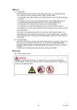
WARNING
The fuser unit becomes extremely hot during operation. Wait until it has cooled down
sufficiently before replacing consumable items. DO NOT remove or damage the
caution label located on or around the fuser.
WARNING
DO NOT
use flammable substances, any type of spray or any organic solvent/liquids
contains alcohol or ammonia to clean the inside or outside of the machine. Doing this
may cause a fire or electrical shock.
Summary of Contents for DCP-9010CN
Page 11: ...Confidential CHAPTER 1 SPECIFICATIONS ...
Page 53: ...Confidential CHAPTER 2 THEORY OF OPERATION ...
Page 90: ...Confidential CHAPTER 3 ERROR INDICATION AND TROUBLESHOOTING ...
Page 201: ...Confidential CHAPTER 4 PERIODICAL MAINTENANCE ...
Page 224: ...Confidential CHAPTER 5 DISASSEMBLY AND ASSEMBLY ...
Page 440: ...Confidential CHAPTER 6 ADJUSTMENTS AND UPDATING OF SETTINGS REQUIRED AFTER PARTS REPLACEMENT ...
Page 446: ...6 5 Confidential 10 Alert warning message appears click Continue Anyway to proceed ...
Page 456: ...Confidential CHAPTER 7 SERVICE FUNCTIONS ...
Page 464: ...7 6 Confidential For color scanning Fig 7 2 ...
Page 487: ...7 29 Confidential Cover page sample Fig 7 13 End page sample Fig 7 14 ...
Page 492: ...7 34 Confidential Color registration adjustment chart Fig 7 16 ...
Page 496: ...7 38 Confidential LED test pattern M68_L Fig 7 18 ...
Page 498: ...7 40 Confidential Fig 7 19 ...
Page 500: ...7 42 Confidential Color test pattern Fig 7 20 MCYK Y C K M YCMK_ _A ...
Page 518: ...Confidential CHAPTER 8 CIRCUIT DIAGRAMS WIRING DIAGRAM ...
Page 521: ...Confidential 8 2 High voltage Power Supply PCB Circuit Diagram SYS HITEK SPH 8N35 2 3 ...
Page 522: ...Confidential 8 3 High voltage Power Supply PCB Circuit Diagram SYS HITEK SPH 8N35 3 3 ...
Page 523: ...Confidential 8 4 High voltage Power Supply PCB Circuit Diagram MURATA MPH3316 1 3 ...
Page 524: ...Confidential 8 5 High voltage Power Supply PCB Circuit Diagram MURATA MPH3316 2 3 ...
Page 525: ...Confidential 8 6 High voltage Power Supply PCB Circuit Diagram MURATA MPH3316 3 3 ...
Page 526: ...Confidential 8 7 Low voltage Power Supply PCB Circuit Diagram 100V ...
Page 527: ...Confidential 8 8 Low voltage Power Supply PCB Circuit Diagram 200V ...
Page 528: ...Confidential 8 9 NCU PCB Circuit Diagram USA Canada ...
Page 529: ...Confidential 8 10 NCU PCB Circuit Diagram Europe Asia Oceania China ...
Page 530: ...Confidential 8 11 NCU PCB Circuit Diagram South Africa Gulf ...
Page 531: ...Confidential 8 12 2 WIRING DIAGRAM Wiring Diagram 1 2 ...
Page 532: ...Confidential 8 13 Wiring Diagram 2 2 ...
Page 590: ...Confidential APPENDIX 3 SERIAL NUMBERING SYSTEM ...
Page 592: ...App 3 2 Confidential Serial number of the LED ASSY Print position Fig App 3 4 Serial number ...
Page 593: ...Confidential APPENDIX 4 SCREW CATALOGUE ...
Page 595: ...Confidential APPENDIX 5 REFERENCES ...
Page 597: ...Confidential APPENDIX 6 GLOSSARY ...


