


7-14
Confidential
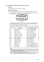
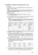
1.4.8 Operational check of control panel button (Function code 13)
<Function>
This function allows you to check if the buttons on the control panel cover ASSY work properly.
<Operating procedure>
(1) Press the
1
and
3
buttons in this order in the initial state of the maintenance mode.
The “00” will appear on the LCD.
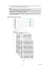
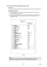
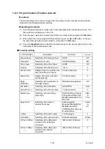
(2) Press the buttons in the order designated in the illustration shown below.
The LCD shows the corresponding number in decimal notation each time a button is
pressed. Check that the displayed number is correct by referring to the illustration below.
When the buttons are pressed in an incorrect order, a warning beep goes off and
“INVALID OPERATE” appears on the LCD at the same time. Press the
Stop/Exit
button,
and the press the correct buttons.
(3) After the last number button is pressed, the machine beeps for one second and returns to
the initial state of the maintenance mode.
■
MFC-9120CN/9125CN/9320CW/9325CW
Fig. 7-6
■
DCP-9010CN/MFC-9010CN
Fig. 7-7
Memo:
When the
Stop/Exit
button is pressed during the operation, the machine beeps for one
second and returns to the initial state of the maintenance mode.
Summary of Contents for DCP-9010CN
Page 11: ...Confidential CHAPTER 1 SPECIFICATIONS ...
Page 53: ...Confidential CHAPTER 2 THEORY OF OPERATION ...
Page 90: ...Confidential CHAPTER 3 ERROR INDICATION AND TROUBLESHOOTING ...
Page 201: ...Confidential CHAPTER 4 PERIODICAL MAINTENANCE ...
Page 224: ...Confidential CHAPTER 5 DISASSEMBLY AND ASSEMBLY ...
Page 440: ...Confidential CHAPTER 6 ADJUSTMENTS AND UPDATING OF SETTINGS REQUIRED AFTER PARTS REPLACEMENT ...
Page 446: ...6 5 Confidential 10 Alert warning message appears click Continue Anyway to proceed ...
Page 456: ...Confidential CHAPTER 7 SERVICE FUNCTIONS ...
Page 464: ...7 6 Confidential For color scanning Fig 7 2 ...
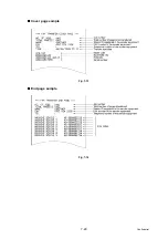
Page 487: ...7 29 Confidential Cover page sample Fig 7 13 End page sample Fig 7 14 ...
Page 492: ...7 34 Confidential Color registration adjustment chart Fig 7 16 ...
Page 496: ...7 38 Confidential LED test pattern M68_L Fig 7 18 ...
Page 498: ...7 40 Confidential Fig 7 19 ...
Page 500: ...7 42 Confidential Color test pattern Fig 7 20 MCYK Y C K M YCMK_ _A ...
Page 518: ...Confidential CHAPTER 8 CIRCUIT DIAGRAMS WIRING DIAGRAM ...
Page 521: ...Confidential 8 2 High voltage Power Supply PCB Circuit Diagram SYS HITEK SPH 8N35 2 3 ...
Page 522: ...Confidential 8 3 High voltage Power Supply PCB Circuit Diagram SYS HITEK SPH 8N35 3 3 ...
Page 523: ...Confidential 8 4 High voltage Power Supply PCB Circuit Diagram MURATA MPH3316 1 3 ...
Page 524: ...Confidential 8 5 High voltage Power Supply PCB Circuit Diagram MURATA MPH3316 2 3 ...
Page 525: ...Confidential 8 6 High voltage Power Supply PCB Circuit Diagram MURATA MPH3316 3 3 ...
Page 526: ...Confidential 8 7 Low voltage Power Supply PCB Circuit Diagram 100V ...
Page 527: ...Confidential 8 8 Low voltage Power Supply PCB Circuit Diagram 200V ...
Page 528: ...Confidential 8 9 NCU PCB Circuit Diagram USA Canada ...
Page 529: ...Confidential 8 10 NCU PCB Circuit Diagram Europe Asia Oceania China ...
Page 530: ...Confidential 8 11 NCU PCB Circuit Diagram South Africa Gulf ...
Page 531: ...Confidential 8 12 2 WIRING DIAGRAM Wiring Diagram 1 2 ...
Page 532: ...Confidential 8 13 Wiring Diagram 2 2 ...
Page 590: ...Confidential APPENDIX 3 SERIAL NUMBERING SYSTEM ...
Page 592: ...App 3 2 Confidential Serial number of the LED ASSY Print position Fig App 3 4 Serial number ...
Page 593: ...Confidential APPENDIX 4 SCREW CATALOGUE ...
Page 595: ...Confidential APPENDIX 5 REFERENCES ...
Page 597: ...Confidential APPENDIX 6 GLOSSARY ...


