


4-3
Confidential
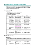
3.
PERIODICAL MAINTENANCE PARTS
3.1 Periodical Maintenance Parts
Periodical maintenance parts are the parts to be replaced periodically to maintain product
quality. These parts would affect the product quality if they loose their functionality even if they
do not appear to be damaged or there is no change in their appearance.
The periodical maintenance parts listed in the table below should be replaced according to the
service life.
* The paper feeding kit includes the separation pad ASSY, pad spring and roller holder ASSY.
When replacing the periodical maintenance parts, each of the counters need to be reset in
order to record the number of replacement times.
(Refer to
“2.1 Resetting the Periodical Maintenance Parts Life” in Chapter7
The number of print pages of the machine can be checked in the log information display
(maintenance mode 80). (Refer to
“1.4.27 Display of the machine’s log” in Chapter 7
The actual number of printed page will vary depending on the type of print job or the paper to
being used. The figures indicated as the approximate life in the table above are worked out
when printing a general business document (in accordance with ISO/IEC 19798) on A4-size
paper.
Parts name
LCD
Approximate life
Replacement
procedure
Fuser unit
Replace Fuser
50,000 pages
Refer to
Paper feeding kit
*
Replace PF Kit
50,000 pages
Refer to
Note:
- Always turn off the power switch of the machine and unplug the power cord from the
power outlet before replacing the periodical maintenance parts.
- If the fuser unit is replaced after an error related to the fuser unit occurs, you need to wait
until the machine sufficiently cools down before replacing the unit. After replacing the
unit, turn ON the machine and leave it for approximately fifteen minutes. This will make
the machine to be released from the error.
Summary of Contents for DCP-9010CN
Page 11: ...Confidential CHAPTER 1 SPECIFICATIONS ...
Page 53: ...Confidential CHAPTER 2 THEORY OF OPERATION ...
Page 90: ...Confidential CHAPTER 3 ERROR INDICATION AND TROUBLESHOOTING ...
Page 201: ...Confidential CHAPTER 4 PERIODICAL MAINTENANCE ...
Page 224: ...Confidential CHAPTER 5 DISASSEMBLY AND ASSEMBLY ...
Page 440: ...Confidential CHAPTER 6 ADJUSTMENTS AND UPDATING OF SETTINGS REQUIRED AFTER PARTS REPLACEMENT ...
Page 446: ...6 5 Confidential 10 Alert warning message appears click Continue Anyway to proceed ...
Page 456: ...Confidential CHAPTER 7 SERVICE FUNCTIONS ...
Page 464: ...7 6 Confidential For color scanning Fig 7 2 ...
Page 487: ...7 29 Confidential Cover page sample Fig 7 13 End page sample Fig 7 14 ...
Page 492: ...7 34 Confidential Color registration adjustment chart Fig 7 16 ...
Page 496: ...7 38 Confidential LED test pattern M68_L Fig 7 18 ...
Page 498: ...7 40 Confidential Fig 7 19 ...
Page 500: ...7 42 Confidential Color test pattern Fig 7 20 MCYK Y C K M YCMK_ _A ...
Page 518: ...Confidential CHAPTER 8 CIRCUIT DIAGRAMS WIRING DIAGRAM ...
Page 521: ...Confidential 8 2 High voltage Power Supply PCB Circuit Diagram SYS HITEK SPH 8N35 2 3 ...
Page 522: ...Confidential 8 3 High voltage Power Supply PCB Circuit Diagram SYS HITEK SPH 8N35 3 3 ...
Page 523: ...Confidential 8 4 High voltage Power Supply PCB Circuit Diagram MURATA MPH3316 1 3 ...
Page 524: ...Confidential 8 5 High voltage Power Supply PCB Circuit Diagram MURATA MPH3316 2 3 ...
Page 525: ...Confidential 8 6 High voltage Power Supply PCB Circuit Diagram MURATA MPH3316 3 3 ...
Page 526: ...Confidential 8 7 Low voltage Power Supply PCB Circuit Diagram 100V ...
Page 527: ...Confidential 8 8 Low voltage Power Supply PCB Circuit Diagram 200V ...
Page 528: ...Confidential 8 9 NCU PCB Circuit Diagram USA Canada ...
Page 529: ...Confidential 8 10 NCU PCB Circuit Diagram Europe Asia Oceania China ...
Page 530: ...Confidential 8 11 NCU PCB Circuit Diagram South Africa Gulf ...
Page 531: ...Confidential 8 12 2 WIRING DIAGRAM Wiring Diagram 1 2 ...
Page 532: ...Confidential 8 13 Wiring Diagram 2 2 ...
Page 590: ...Confidential APPENDIX 3 SERIAL NUMBERING SYSTEM ...
Page 592: ...App 3 2 Confidential Serial number of the LED ASSY Print position Fig App 3 4 Serial number ...
Page 593: ...Confidential APPENDIX 4 SCREW CATALOGUE ...
Page 595: ...Confidential APPENDIX 5 REFERENCES ...
Page 597: ...Confidential APPENDIX 6 GLOSSARY ...


