26
Section D – Electrical Components
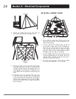
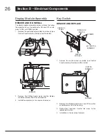
Display Module Assembly
REMOvE AND RE-INSTALL
The display module assembly contains switches that allow
the operator to turn the compactor ON and OFF and to
select HOLD or NORMAL mode.
Remove the control panel assembly from the unit (see
1.
Control Panel Assemby, Remove and Re-install).
SCREWS
Remove five Phillips head screws and the display
2.
module assembly from the control panel.
Installation assembly is the reverse of removal.
3.
Key Switch
REMOvE AND REPLACE
SCREWS
CONTROL
PANEL
INTERLOCK
SWITCH
KEY SWITCH
ASSEMBLY
DISPLAY
MODULE
KEY
Remove the control panel assembly (see Control
1.
Panel Assembly, Remove and Re-install).
SCREWS
SWITCH
ASSEMBLY
Remove two Phillips head screws and lift the switch
2.
assembly away from the housing.
Noting their locations, transfer the wires to the
3.
replacement switch.
Installation is the reverse of removal.
4.


