BRIGHT Coop Cage Unloading System Operator And  Maintenance Manual Download Page 73

Schematics

Cage Unloading System

73

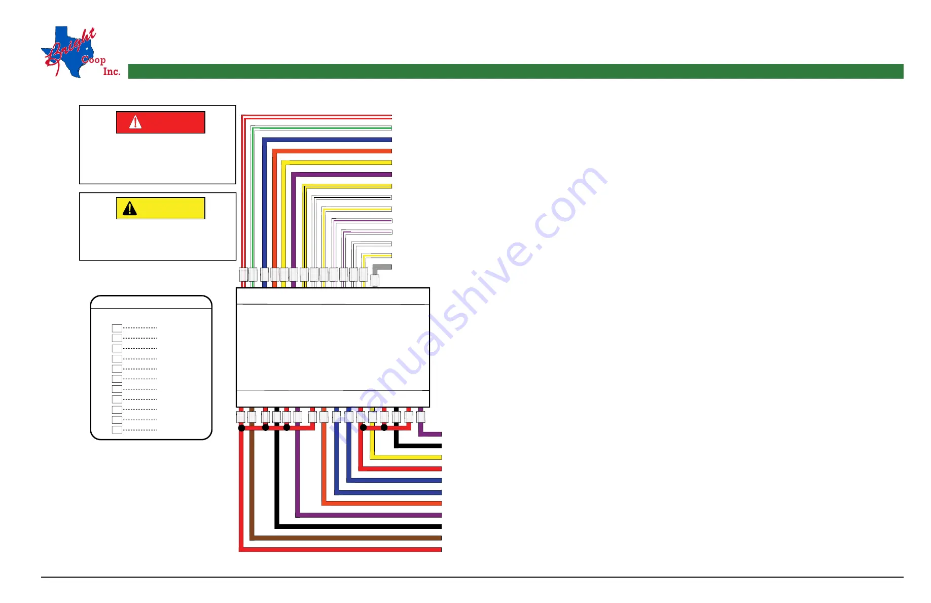
ELECTRICAL SCHEMATIC SMART RELAY (091-21961W) 

I/O DESCRIPTION FOR PROGRAMMABLE RELAY DATED - JUNE-2012

Wire with Two Letters 

is Striped

WIRE COLOR CODE CHART

COLOR CODE - DESCRIPTION


B
C
D
E

G
H
M
N
R

ORANGE
WHITE
PINK
GREY
GREEN
BLUE
YELLOW
PURPLE
BROWN
BLACK
RED

24V DC+ (FROM BLOW FUSE 1A)
24 V DC- (FROM POWER SUPPLY)
FENCING GATE SENSOR 1 (MUST BE ON WHEN THE GATE IS CLOSED)
FENCING GATE SENSOR 2 (MUST BE ON WHEN THE GATE IS CLOSED)
FENCING GATE SENSOR 3 (MUST BE ON WHEN THE GATE IS CLOSED)
FENCING GATE SENSOR 4 (MUST BE ON WHEN THE GATE IS CLOSED)
OPERATOR GATE SENSOR (MUST BE ON WHEN THE GATE IS CLOSED)
NOT USED
NOT USED
NOT USED
WASHER CRADLE (MUST BE ON WHEN THE CRADLE IS IN THE POSITION)
WASHER CARRIAGE HOME POSITION (MUST BE ON WHEN THE CARRIAGE IS HOME)
WASHER CARRIAGE END OF TRAVEL POSITION (MUST BE ON WHEN THE CARRIAGE IS IN THE END OF TRAVEL POSITION)
RESET SWITCH (TURN ON WHEN DEPRESSING THE RESET BUTTON)
 

WATER VALVE SOLENOID (ENERGIZED WHEN THE CARRIAGE IS IN MOTION)
WASHER CARRIAGE REVERSE SOLENOID (MOVES CARRIAGE FORM END OF TRAVEL TO HOME POSITION)
WASHER CARRIAGE FORWARD SOLENOID (MOVES CARRIAGE FROM HOME TO END OF TRAVEL POSITION)
120V AC (L) (FROM WATER PUMP SWITCH IN CONTROL PANEL))
NOT USED
NOT USED
CRADLE SELECTOR SWITCH POWER
NOT USED
NOT USED
NOT USED
120V AC (L) (FROM MAIN 10A BREAKER)

SMART RELAY FOR UNLOADING SYSTEM


WITH WASHER

(091-21961W)

+ _ |1 |2 |3 |4 |5 |6 |B |C |D |E |F |G _ _

1 2 1 2 1 2 1 2 1 2 1 2 1 2 1 2

Q2

Q1

Q3 Q4

Q5

Q6 Q7

Q8

RB BE

A G

GN BN BG BH

F

R

R N R H

A F F

BG D

M

R G R N

H

BH BN

H

R

R

NEVER  ATTEMPT  TO  SERVICE  OR 

MAINTAIN  THE  UNLOADING  SYSTEM  IF 

THE  MAIN  POWER  SOURCE  IS 

ENERGIZED.  USE  PROPER  LOCKOUT/ 

TAGOUT PROCEDURES.

DANGER

This  Smart  Relay  Schematics 

contains  120  Volt  AC+  and  24  Volt 

DC- Wiring.
 

CAUTION

Summary of Contents for Cage Unloading System

Page 1: ...arga de Jaulas Operator s Maintenance Manual Manual del Operador y Mantenimiento Bright Coop Inc 803 W Seale St Nacogdoches TX 75964 Phone 936 564 8378 Fax 936 564 3281 Info brightcoop com Printed in...

Page 2: ...ator s Maintenance Manual Cage Unloading System Bright Coop Inc 803 W Seale St Nacogdoches TX 75964 Phone 936 564 8378 Fax 936 564 3281 Info brightcoop com Printed in the U S A 2 1 2019 BC 091 00950_E...

Page 3: ...30 MAINTENANCE 40 MAINTENANCE UNLOADING SYSTEM 40 MAINTENANCE SCHEDULE QUICK REFERENCE 47 RECOMMENDED HYDRAULIC FLUID 48 WARRANTY AND LIMITATIONS OF LIABILITY 49 DUMPER TROUBLESHOOTING 51 SCHEMATICS...

Page 4: ...Operator s Maintenance Manual Cage Unloading System 4 RIGHT HAND CONFIGURATION LEFT HAND CONFIGURATION CONFIGURATION...

Page 5: ...OPERATOR S PLATFORM WASHER BOTTOM FIRST OUTGOING CONVEYOR RECEIVING CAGE HANGING BELT EXTENSION BELT SAFETY ARM INCOMING CONVEYOR OUTGOING CONVEYOR HYDRAULIC DOOR CLOSER DUMPER SECTION LIFTING TRANSF...

Page 6: ...Operator s Maintenance Manual Cage Unloading System 6 to Be Knowledgeable to Be Safe for Your Safety for The Safety of Others is The Operator s Responsibility Study Study Study Study Safety...

Page 7: ...ety of others rests solely on the operator 4 Only one 1 operator at a time should be allowed on the operator s platform Do not allow any other person on the platform at any time 5 Keep all body parts...

Page 8: ...em 7 Always use handrails when walking on the unloading system for any reason 8 Wear proper attire when performing service or maintenance Loose clothing should not be worn while servicing or maintaini...

Page 9: ...o options included with your system See Figures 3 4A 4B 4C RIGHT HAND SIDE SYSTEM AS OPPOSITE LEFT HAND SIDE SYSTEM AS SHOWN SEE NEXT PAGE FOR CONTROL PANEL OPERATOR CONSOLE FIGURE 3 FORWARD RIGHT DOW...

Page 10: ...4A FIGURE 4B FIGURE 4C CONTROL PANEL W O WASHING SYSTEM CONTROL PANEL W WASHING SYSTEM CONTROL PANEL WITHOUT DOOR OR WASHING SYSTEM LEFT HAND SIDE SYSTEM RIGHT HAND SIDE SYSTEM LEFT HAND SIDE SYSTEM...

Page 11: ...ction toward the operator Pushing the lever away from you will move the chicken cage out of the dumper section and onto the incoming conveyor THE ORDER OF THE LEVERS IS GIVEN BY STARTING FROM THE CON...

Page 12: ...tom out 4 FOURTH LEVER controls the lift transfer chain conveyor Pulling the lever toward you will lift and move the chicken cage from the dumper section toward the washer section Pushing the lever aw...

Page 13: ...Operator Console Functions Controls Cage Unloading System 13 DOWN UP FIGURE 5 LIFT TRANSFER CHAINS LEVER FUNCTIONS CONT D...

Page 14: ...bottom Pulling the lever toward you will move the chicken cage toward the operator s platform ELECTRIC CONTROL PANEL THE OPERATOR MUST BE FAMILIAR WITH THE CONTROL PANEL IN REGARDS TO THE OPTIONS ON T...

Page 15: ...g pump 1 as a primary Pump 2 should be used one 1 day a week to make sure it is in working condition in case pump 1 fails The switch for the door closer must be in the ON position for this device to o...

Page 16: ...the safety gates has been opened and closed BALL VALVE The ball valve is used to disable the hydraulic components in the cage unloading system This ball valve should be locked out whenever an operato...

Page 17: ...wer unit switch is in the OFF position We recommend using pump 1 as a primary Pump 2 should be used one 1 day a week to make sure it is in working condition in case pump 1 fails The switch for the doo...

Page 18: ...o energize the relays that powered all electrical valves This action must be performed after the master power is turned ON and after one of the safety gates has been opened and closed THE OPERATOR MUS...

Page 19: ...ASHER TILT SELECTOR SWITCH The cradle of the washer section is tilted upward by turning the selector switch to UP Note that the cradle must be tilted until the hydraulic cylinders bottom out When the...

Page 20: ...ause the system to be unsafe to operate 3 The operator should visually check under and around the unloading system to make sure that nobody is on and or under it and or inside the safety fence before...

Page 21: ...t go down at this time turn the master switch OFF and report the issue to your supervisor and or the maintenance manager 2 If your system is equipped with an automatic hydraulic door closer make sure...

Page 22: ...button the audible alarm and the two 2 red flashing lights should stop and the safety arm should go up With the help of another person helper ask the helper to open and close the gates of the safety...

Page 23: ...this is working properly open the ball valve handle horizontal and push and release the safety shutdown reset button After you push and release the button the audible alarm and the 2 red flashing ligh...

Page 24: ...is set at the loading area on the incoming conveyor the unloading system operator may pull and hold the first INCOMING ROLLS and second DUMPER ROLLS hydraulic levers simultaneously This action will mo...

Page 25: ...g area and the forklift operator will be able to set another loaded chicken cage onto the incoming conveyor and make a continuous flow See Figure 9 Note that the unloading system operator should only...

Page 26: ...RATOR TO NEVER SHOVE A CHICKEN CAGE FROM THE LOADING AREA TO SET ANOTHER LOADED CAGE ON THE INCOMING CONVEYOR See figure 10 THE FORKLIFT OPERATOR SHOULD ALWAYS WAIT UNTIL THE UNLOADING SYSTEM OPERATOR...

Page 27: ...third DUMPER TILT hydraulic lever and hold it until the cradle cyl inders are fully retracted The cylinders are fully retracted when the cradle stops tilting downward Then release the lever See Figur...

Page 28: ...EMPT TO SET A LOADED CHICKEN CAGE ON THE DUMPER SECTION WHILE THE LIFTING CHAIN CONVEYOR IS IN THE UP POSITION THIS MAY RESULT IN DAMAGE TO THE CONVEYOR See Figure 13 UNLOADING SYSTEM WITH CAGE WASHIN...

Page 29: ...it If there is a chicken cage at the unloading area release the lever before the cages hit each other Note that if your system is equipped with a hydraulic door closer you do not have to perform any...

Page 30: ...the master switch OFF and report the issue to your supervisor and or the maintenance manager 2 If your system is equipped with an automatic hydraulic door closer make sure the door closer switch on t...

Page 31: ...shutdown reset button After you push and release the button the audible alarm and the two 2 red flashing lights should stop and the safety arm should go up With the help of another person helper ask...

Page 32: ...to your supervisor and or maintenance manager If this is working properly open the ball valve handle horizontal and push and release the safety shutdown reset button After you push and release the bu...

Page 33: ...ng conveyor See Figure 7 9 After the chicken cage is set at the loading area on the incoming conveyor the unloading system operator may pull and hold the first INCOMING ROLLS and second DUMPER ROLLS h...

Page 34: ...ing area and the forklift operator will be able to set another loaded chicken cage onto the incoming conveyor and make a continuous flow See Figure 9 Note that the unloading system operator should onl...

Page 35: ...GE WASHING SYSTEM CONT D INSTRUCT THE FORKLIFT OPERATOR TO NEVER SHOVE A CHICKEN CAGE FROM THE LOADING AREA TO SET ANOTHER LOADED CAGE ON THE INCOMING CONVEYOR See figure 10 THE FORKLIFT OPERATOR SHOU...

Page 36: ...e third DUMPER TILT hydraulic lever and hold it until the cradle cyl inders are fully retracted The cylinders are fully retracted when the cradle stops tilting downward Then release the lever See Figu...

Page 37: ...SYSTEM WITH CAGE WASHING SYSTEM CONT D NEVER ATTEMPT TO SET A LOADED CHICKEN CAGE ON THE DUMPER SECTION WHILE THE LIFTING CHAIN CONVEYOR IS IN THE UP POSITION THIS MAY RESULT IN DAMAGE TO THE CONVEYO...

Page 38: ...the ON position If the switch is in the OFF position turn it to the ON position If the switch is in the ON position but no water is coming out of the nozzles turn the water pump switch OFF and report...

Page 39: ...he outgoing conveyor at this time See Figure 14 NOTE For efficiency the forklift operator should use the following steps 1 Get a loaded chicken cage from the trailer 2 Set the loaded chicken cage on t...

Page 40: ...T IN DAMAGE TO THE UNLOADING SYSTEM SERIOUS INJURIES OR DEATH ALWAYS ADHERE TO THE CONFINED SPACE PROCEDURES IF YOU HAVE TO WORK UNDERNEATH THE UNLOADING SYSTEM MAKE ABSOLUTELY SURE THAT THE UNLOADING...

Page 41: ...STEM FOR TEST AFTER ANY MAINTENANCE OR REPAIRS IF THE LOCK REMAINS IN THE LOCK POSITION AND THE DUMP ER TILT LEVER IS ACTIVATED THE CRADLE WILL BE DAMAGED UNLESS YOU HAVE AN INTERLOCK SYSTEM THAT SHUT...

Page 42: ...es described in step 2 are proven to be working properly push and release the safety shutdown reset switch button 8 Open and close the operator s safety gate The audible alarm should sound two 2 red l...

Page 43: ...et button 23 Repeat from step 15 until all safety gates are proven to work properly HYDRAULIC POWER UNIT 24 Verify the power unit oil level every day before energizing the system See figure 15 If the...

Page 44: ...ced after every 250 hours of operation Replace the hydraulic fluid once a year 26 Verify and adjust if necessary the tension of the main chain See Figure 16 To adjust the tension of the lifting transf...

Page 45: ...CONT D MAKE ABSOLUTELY SURE THAT NOBODY REMAINS ON AND OR UNDER THE UNLOADING SYSTEM NOBODY REMAINS IN SIDE THE SAFETY FENCE AND THAT ALL SAFETY GATES ARE CLOSED BEFORE TURNING THE MAIN POWER SOURCE...

Page 46: ...osition 34 Turn the main power source OFF and lockout tagout 35 Go back to step 26 36 Turn the master switch to the OFF position 37 Turn the main power source OFF and lockout tagout MAINTENANCE UNLOAD...

Page 47: ...veyor drive chains X Lubricate transfer chains X Grease bearings X Grease tilt cylinder pivots Cradles X Hydraulic filters Kidney loop return pressure X Pins and rods of belts X Carriage washer slidin...

Page 48: ...rol 215 B Hydrol 315 C Chevron Chevron HYD 32 A Chevron HYD 46 B Chevron HYD 68 C Cities Service Pacemaker XD 15 A Pacemaker XD 20 B Pacemaker XD 30 C Continental Super Hydraulic 15 A Super Hydraulic...

Page 49: ...iginal purchaser for a reasonable amount of labor involved at the rate of 30 00 U S currency per hour if the origi nal purchaser or authorized employee of the original purchaser mails or faxes a copy...

Page 50: ...ost time personal injury or other expenses whether or not resulting directly or indirectly from claimed defects covered by the above written warranty No person is authorized to make on behalf of BCI a...

Page 51: ...lace faulty sensor cable 091 20352 1 2 3 8 Replace smart relay 091 21961T 9 Check and replace as needed Machine will not start or breaker smart relay box will not light up 1 Master power switch off 2...

Page 52: ...control valve 810 00192 6 Replace pressure reducing valve 810 00227 7 Replace cylinder 170 00002 8 Replace smart relay 091 21961T Cradle creeping up 1 Faulty check valve 2 Cylinder bypassing 1 Replace...

Page 53: ...21961T Transfer chains not moving left or right 1 Tripped or faulty breaker 2 Blown hose 3 Broken drive chain 4 Worn sprocket 5 Chain stuck to guide rail 6 Worn out cages 7 Faulty coil 8 Faulty hydrau...

Page 54: ...closer paddle 5 Faulty coil 6 Faulty hydraulic valve 7 Faulty flow control valve 8 Faulty sensor 9 Faulty smart relay 10 Worn out cylinder 1 Turn switch on 2 Check for tripped or faulty breaker 190 00...

Page 55: ...10 Faulty hydraulic motor 11 Faulty smart relay 12 Worn out cages 1 Replace roller see parts manual 2 Replace sprocket see parts manual 3 Replace chain 110 00001H 4 Replace hose see parts manual 5 Re...

Page 56: ...or 14 Faulty knee lever valve on hanging belt 1 Adjust take up and or remove belt section as needed 2 Replace hose see parts manual 3 Replace chain 110 00001H 4 Replace sprocket see parts manual 5 Rep...

Page 57: ...or 14 Faulty knee lever valve on hanging belt 1 Adjust take up and or remove belt section as needed 2 Replace hose see parts manual 3 Replace chain 110 00001H 4 Replace sprocket see parts manual 5 Rep...

Page 58: ...nual 8 Replace Intralox sprocket 050 00071 9 Replace coil 091 24340 10 Replace cartridge valve 091 24338 11 Replace flow control 330 00272 12 Replace motor 450 00004 13 Replace knee lever valve 810 00...

Page 59: ...filter 4 Faulty return filter head 5 Faulty pump 1 Check ball valve in tank 2 Replace return oil filter 230 00060 3 Check gage and replace as needed 230 00059 4 Replace return filter head 230 00022 5...

Page 60: ...Schematics Cage Unloading System 60 SCHEMATICS...

Page 61: ...Schematics Cage Unloading System 61 ELECTRICAL SCHEMATIC TRANSFER CHAIN 091 21967 01 DATED FEBRUARY 2019...

Page 62: ......

Page 63: ...Schematics Cage Unloading System 63 ELECTRICAL SCHEMATIC TRANSFER CHAIN 091 21967 01 DATED FEBRUARY 2019...

Page 64: ......

Page 65: ...Schematics Cage Unloading System 65 ELECTRICAL SCHEMATIC TRANSFER CHAIN AND WASHER 091 21964 01 DATED OCTOBER 2016...

Page 66: ......

Page 67: ...Schematics Cage Unloading System 67 ELECTRICAL SCHEMATIC TRANSFER CHAIN AND WASHER 091 21964 02 DATED OCTOBER 2016...

Page 68: ......

Page 69: ...TRANSFORMER NOT REQUIRED IF EXTERNAL 120V CONTROL POWER IS AVAILABLE FAN MOTOR IS 3 4HP ON CERTAIN MODELS 1 LIQUID LEVEL SWITCH N 3 2 1 3 HEATER 1500W OFF PUMP 1 1 2 1 CONTROL SWITCH X2 BRIGHT COOP B...

Page 70: ......

Page 71: ...R MUST BE ON WHEN THE TRANSFER CHAIN LEVER IS PULLED RESET SWITCH TURN ON WHEN DEPRESSING THE RESET BUTTON TRANSFER CHAIN LIFT ENERGIZES TRANSFER CHAIN LIFT SOLENOID TRANSFER CHAIN REVERSE ENERGIZES T...

Page 72: ......

Page 73: ...IS HOME WASHER CARRIAGE END OF TRAVEL POSITION MUST BE ON WHEN THE CARRIAGE IS IN THE END OF TRAVEL POSITION RESET SWITCH TURN ON WHEN DEPRESSING THE RESET BUTTON WATER VALVE SOLENOID ENERGIZED WHEN...

Page 74: ......

Page 75: ...Schematics Cage Unloading System 75 HYDRAULIC SCHEMATIC CAGE UNLOADING SYSTEM WITHOUT WASHER 091 23900...

Page 76: ......

Reviews: