Not for
Reproduction
4
3
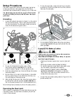
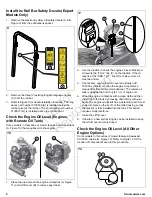
2. Connect the black negative battery cable (B) to the
negative battery post.
Install the Ground Speed Control Levers
This procedure is only necessary if the ground speed control
levers are not factory-installed on your unit.
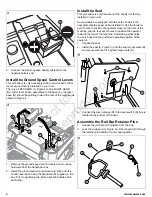
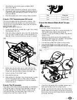
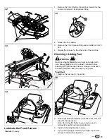
There is a LEFT-HAND (A, Figure 4) and a RIGHT-HAND
(B) control lever. When assembled to the base (C), the lever
base (D) should be pointing toward the rear of the machine as
shown in Figure 4.
4
1. Remove the ground speed control levers and mounting
hardware from the handle bar box.
2. Install the ground speed control levers (A & B) onto the
control lever base using the hardware (E) supplied in the
box. Prior to tightening the bolts, align the handles with
each other.
Install the Seat
This procedure is only necessary if the seat is not factory-
installed on your unit.
Some models are equipped with two sets of holes in the
seat plate that the seat can be installed in. Use the forward
set of holes to position the operator closer to the front of the
machine and the rear set of holes to position the operator
towards the rear of the machine. Determining what holes
to use is based on the preferred operating position of the
operator.
1. Unpack the seat.
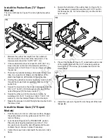
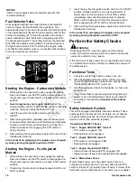
2. Install the seat (A, Figure 5) onto the seat mount plate (B)
and secure with the 5/16 nylock flange nuts (C).
5
3. Connect the wire harness (D) to the seat switch (E) that is
located in the bottom of the seat.
Assemble the Roll Bar Retainer Pins
1. Unpack the roll bar and hardware from the box.
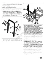
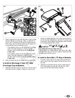
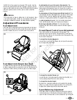
2. Lock the snap end (A, Figure 6) of the lanyard (B) through
the retainer pin handle (C) and snap together.
6


