


13
5
ADJUST ARMATURE AIR GAP
1. Rotate flywheel until magnet is under armature lamina-
tions.
2. Place thickness gauge, .008”-.012” (0.20-.30 mm) be-
tween magnet and armature laminations, Fig. 14.
3. Loosen mounting screw so magnet will pull armature
down against thickness gauge.
a. Torque screws to 25 in. lbs. (3.0 Nm).
4. Rotate flywheel to remove thickness gauge.
5. Repeat for second armature.
Fig. 14
−
Adjust Armature Air Gap
THICKNESS
GAUGE
INSTALL CYLINDER HEADS
1. Place cylinder head gasket over alignment dowels on
cylinder block.
2. Install cylinder head assembly, Fig. 15.
a. Torque head bolts in sequence shown to 220 in.
lbs. (25.0 Nm).
3. Install push rods. Make sure push rods are inserted in
recess in tappets.
Note:
Intake push rods are aluminum.
Fig. 15
−
Install Cylinder Head
3
4
5
1
2
4. Compress valve springs and insert push rods into re-
cess in rocker arm adjustment screws, Fig. 16.
Fig. 16
−
Insert Push Rods
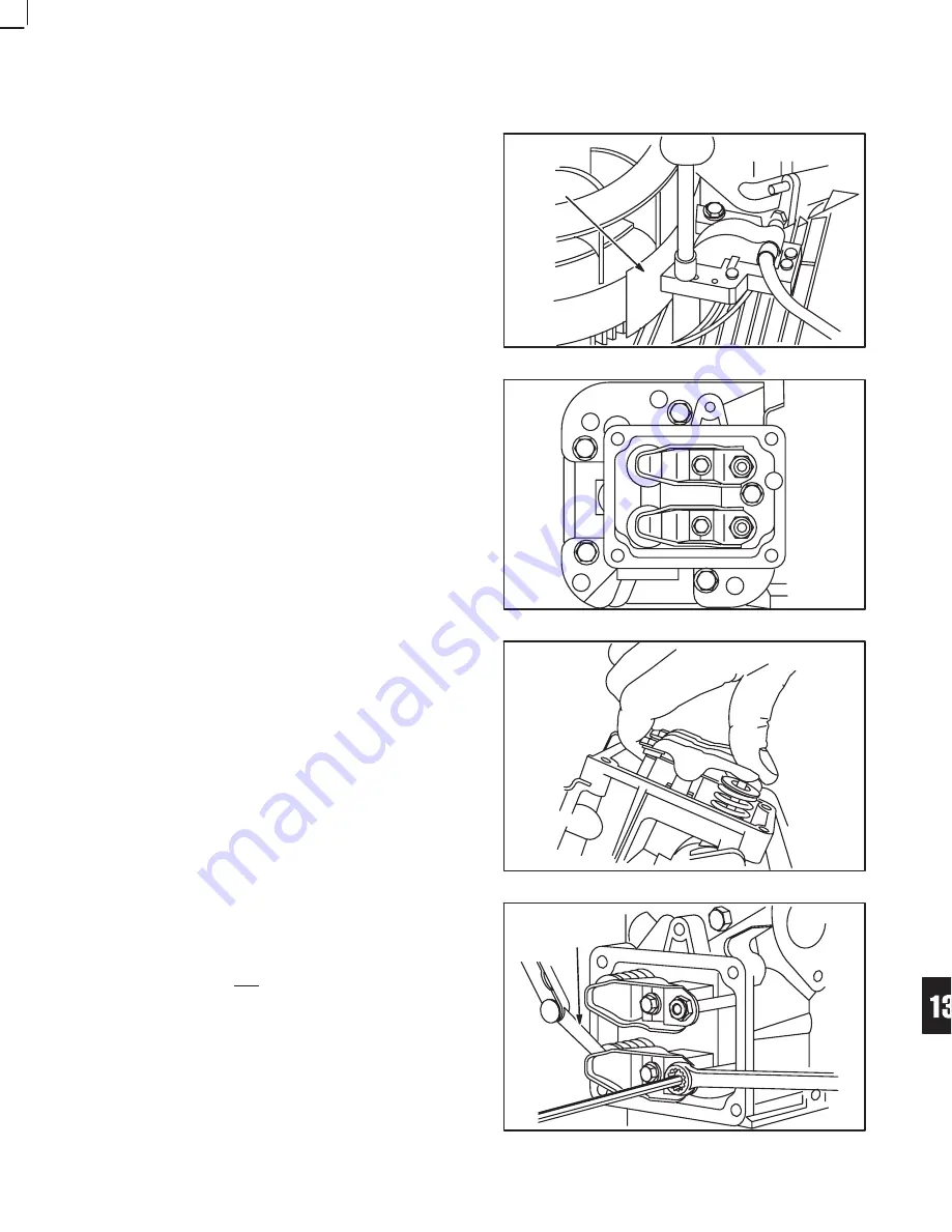
ADJUST VALVES
1. Set No. 1 cylinder at 1/4” (6.4mm) past TDC, compres-
sion stroke.
a. Adjust valves and check, Fig. 17.
Valve Clearance (cold) IN
and
EX
.005” (0.13 mm)
b. Torque adjusting screws and jam nuts to 60 in. lbs.
(7.0 Nm).
2. Set No. 2 cylinder at TDC, compression stroke.
a. Repeat for No. 2 cylinder.
Fig. 17
−
Adjust Valves
.005”
TSM
Summary of Contents for 405777 Series
Page 1: ...TSM ...