


10
3
Cylinder Finish (Cross Hatch)
The finishing stones are used after the cylinder bore has
been resized to within.0015” (.04 mm) of the desired size or
when reconditioning a cylinder bore. The finishing stones
will produce the correct cross hatch necessary for proper
lubrication. The correct cross hatch angle is approximately
45 degrees, Fig. 4.
It is recommended that the cylinder bores be reconditioned
to restore the cross hatch when new piston rings are to be
installed in a cylinder that is within specification. Be careful
not to hone oversize or it will be necessary to resize the
cylinder.
NOTE: To produce the proper cross hatch finish use a drill
speed of approximately 200 RPM and 40-60 strokes per
minute. Lubricate hone liberally to prevent build up on
finishing stones.
Fig. 4
−
Cylinder Cross Hatch
APPROXIMATELY 45
°
45
°
Cleaning
IT IS MOST IMPORTANT THAT THE ENTIRE CYLINDER AND CRANKCASE BE THOROUGHLY CLEANED AFTER
HONING.
First wash the cylinder and crankcase carefully in a solvent such as kerosene or commercial solvent. Then
thoroughly wash cylinder and crankcase using a stiff brush with soap and hot water. Rinse thoroughly with hot running water.
Repeat washing and rinsing until all traces of honing grit are gone.
Honing grit is highly abrasive and will cause rapid wear to all of the internal components of the engine unless it is completely
removed.
NOTE: When cylinder and crankcase have been thoroughly cleaned, use a clean white rag or napkin and wipe the cylinder
bore. If honing grit is present it will appear as a gray residue on rag. If any honing grit is evident, re-wash and rinse entire cylinder
and crankcase and check again. When there is no trace of honing grit on rag, the cylinder is properly cleaned. Then oil cylinder
bore to prevent rusting.
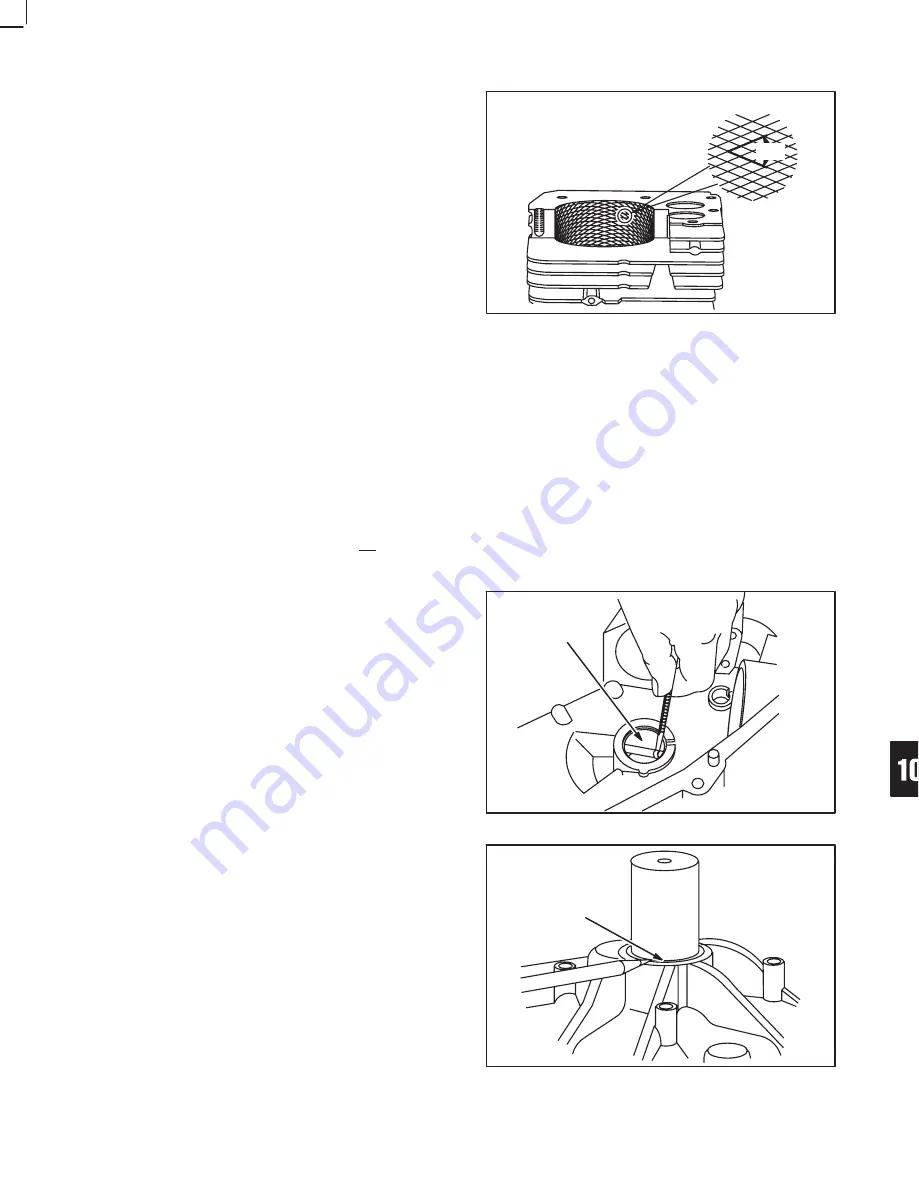
BEARINGS
Check Mag Bearing
Check DU magneto bearing for damage. Check for wear
using plug gauge Tool #19219, Fig. 5. Try gauge at several
locations. If plug gauge is not available see reject
dimension below.
Reject Dimension: 1.383” (35.12 mm)
Replace bearing if damaged or worn.
Fig. 5
−
Check Mag Bearing
1.383” (35.12 MM)
Remove Mag Bearing
Insert bushing driver, Tool #19226 into bearing from oil seal
side. Place a reference mark on driver to indicate proper
depth of bushing when installing new bushing.
1. Place cylinder on cylinder support, Tool #19227 with
large opening facing DU bearing, Fig. 6.
2. Press out bearing with bushing driver, Tool #19226.
Fig. 6
−
Remove Mag Bearing
REFERENCE
LINE
TSM
Summary of Contents for 405777 Series
Page 1: ...TSM ...