


Not for
Reproduction
9.
If the desired results are not observed, obtain the
Master Seat Cutter Kit (Part No. 19547) and proceed
as follows:
NOTE: Carefully read manufacturer's directions for
proper assembly and use of tool.
A. Install the proper sized pilot in the valve guide.
NOTE: Do not drop the cutter onto the valve seat
during installation or removal, as the blades may
cause seat damage that requires additional cutting.
NOTE: Applying too much pressure or rotating the
cutter too fast will produce chatter marks that
adversely affect sealing integrity. Rotate the cutter
slowly, so that it takes about three seconds to make
one complete rotation.
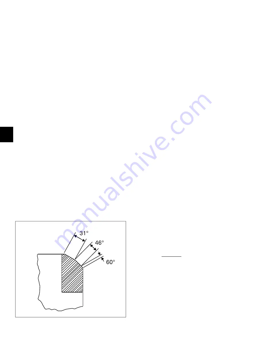
B. See Figure 56. Install the 60° cutter on the pilot to
make the bottom-narrowing cut. Rotate the cutter
three of four turns, so that it cuts all the way around
the valve seat.
C. Install the 31° cutter to make the top-narrowing cut.
D. Install the 46° base angle cutter and cut the seat
contact area until it is approximately 0.047-0.063
inches (1.19-1.59 mm) wide.
E. Use low pressure compressed air to thoroughly
remove all cutting chips and metal shavings.
Remove pilot from valve guide.
F. Lap the valve face and seat a second time to verify
location and width of the seat contact area.
G. If the seat contact area is too narrow, recut using
the 46° base angle cutter.
H. If the seat contact area is too wide, repeat steps
9(B) and 9(C).
10. Perform steps 8-9 on the exhaust valve.
56
Valve Springs
1.
Inspect valve springs for broken or discolored coils.
Replace springs if either of these conditions are found.
2.
Set the intake and exhaust valve springs on a level
surface and use a straightedge to check for proper
squareness and equivalent height. Too much height
may correspond to a reduction in spring pressure which
results in sluggish valve action.
Valve Spring Retainers
1.
Inspect parts for rust pits or corrosion. Replace as
necessary.
2.
Inspect inside diameter for damage or excessive wear.
Center must be well defined without distortion.
Tappets, Push Rods, and Rocker Arms
1.
Inspect tappet sockets for signs of scuffing, pitting or
general wear.
2.
Tappet faces may appear to have smooth surfaces, but
still have concave wear. Hold a straight edge across
the tappet face. Any concave wear found on the tappet
faces may also indicate worn camshaft lobes.
3.
Roll push rods on a flat surface to determine if they are
bent. Replace push rods that are bent, dented, broken
or discolored. Replace the push rod if the ball ends
show signs of excessive wear or damage. For best
practices, replace push rods in pairs.
4.
Check the push rod guide plate for cracks or other
damage. Replace if necessary.
5.
Check rocker arms for uneven wear or pitting where
contact is made with the valve stem tips. Check for
concave wear where rocker arms contact the push rod
ends. Replace the rocker arm if excessive wear is found
at either location, or if pitted, deformed, or scored.
Carburetor and Muffler Studs
1.
Inspect carburetor and muffler studs. Replace studs if
broken, bent, or if severe thread damage is observed.
2.
Replace a carburetor stud as follows:
A. Retrieve the two hex flange nuts removed from the
studs during air cleaner removal.
B. Thread first nut onto stud upside down.
C. Thread second nut onto stud right-side up until it
makes firm contact with the first.
D. Rotate inside nut in a counter-clockwise direction
until stud is loose.
50
6
Summary of Contents for 130G00
Page 1: ...N o t f o r R e p r o d u c t i o n ...
Page 2: ...N o t f o r R e p r o d u c t i o n ...
Page 6: ...N o t f o r R e p r o d u c t i o n ...
Page 8: ...N o t f o r R e p r o d u c t i o n ...
Page 26: ...N o t f o r R e p r o d u c t i o n 20 2 ...
Page 32: ...N o t f o r R e p r o d u c t i o n 26 3 ...
Page 44: ...N o t f o r R e p r o d u c t i o n TOP END DISASSEMBLY 41 38 5 ...
Page 50: ...N o t f o r R e p r o d u c t i o n 44 5 ...
Page 90: ...N o t f o r R e p r o d u c t i o n 123 84 8 ...
Page 100: ...N o t f o r R e p r o d u c t i o n 94 8 ...
Page 108: ...N o t f o r R e p r o d u c t i o n This page is intentionally left blank 102 9 ...
Page 109: ...N o t f o r R e p r o d u c t i o n This page is intentionally left blank 103 9 ...
Page 110: ...N o t f o r R e p r o d u c t i o n This page is intentionally left blank 104 9 ...
Page 111: ...N o t f o r R e p r o d u c t i o n This page is intentionally left blank 105 9 ...


