


5
Estimated Tidal Volume
The estimated tidal volume is a calculated value, based on time and
calibrated flow values. The constant leak through the breathing circuit
exhalation port is subtracted from this calculation to give a reasonably
accurate estimation of tidal volume. If a different exhalation port is used (a
ventilated mask for example) this calculation may be affected by the possible
change in exhalation port flow rate. This must be taken into consideration
when reading the tidal volume.
A ventilated mask with a higher flow exhalation port will cause the estimated
flow reading to be slightly higher than normal.
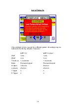
Inspiratory Trigger
The NIPPY+ employs flow triggering, detecting the start
of the patients’
inspiratory effort when the flow rate exceeds the level set by the Inspiratory
Trigger sensitivity.
Expiratory Trigger
The expiratory trigger is used in Pressure Support mode only. Towards the
end of inspiration, when the inspiratory flow rate drops to the baseline
(standing flow caused by exhale port leak) minus the expiratory trigger
sensitivity the ventilator will cycle into the expiratory phase.
The inspiratory and expiratory effort required to cycle the ventilator can be
adjusted via the Trigger option in the Menu.
For simplicity the trigger sensitivity is scaled 1
–10, with 10 being the most
difficult.
Battery Charging
Both internal and external batteries are of Lithium Ion construction. Charging is
fully automatic. When the ventilator is connected to mains power but not
running, batteries will be charged continuously. The internal battery is charged
to approx. 95%, and then the external battery (if present) is charged to the same
level, before switching back to internal to complete the charge. The charge will
be terminated when both batteries are fully charged.
Whilst the ventilator is running, the batteries are charged during the EPAP
period of the breathing cycle.
When the ventilator is switched off it is in standby mode. It will “wake up” every
16 seconds to check the state of its batteries and start a charge sequence if
necessary.
Summary of Contents for Nippy 3+
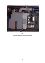
Page 18: ...16 Fig 3 Inside the base with the control board removed...
Page 32: ...30...
Page 33: ...31 Circuit Diagrams...
Page 34: ...32...
Page 35: ...33 0901 0901 PCB assembly for Control Board primary side 16 11 07...
Page 36: ...34 0901 0901 PCB assembly for Control Board secondary side 16 11 07...
Page 37: ...35 0756 C 17 02 04 A4 1 1 Component Layout for Nippy 3 Command Board 0756 C...
Page 38: ...36...
Page 39: ...37...
Page 40: ...38...
Page 41: ...39...
Page 42: ...40...
Page 43: ...41...
Page 44: ...42 4 7 0 0 u F...