


43
SPECIFICATIONS
Supply Voltage
-
100 - 240 V alternating current
Supply Frequency
-
47 - 63 Hz
Maximum Input Current
-
0.40
– 1.0 Amperes
Fuse Ratings
-
2 x T 1.6 A 20mm
Dimensions (mm)
Length
–
297, Width
– 223, Height
- 132
Weight
-
3.6 kg (4.5 kg with internal battery)
Ambient Operating Temperature
-
40o C 104oF Max
Digital Output
-
RS232 Isolated to 1500 Volts
All displayed readings expressed as
-
ATPD
Max. Output Pressure
-
38 cmH
2
O (30 cmH
2
O Jr+)
(44cm fault condition)
Calibrated pressure Range
-
0
– 38 cmH
2
O (0-30 Jr+)
Accuracy of pressure reading
-
+/- 3.0% F.S. +/-1% zero
Max. Output Flow
-
200 L/min. (unrestricted)
Max Volume Reading
-
2000 millilitres
Accuracy of volume reading
-
Estimated
Accuracy of Flow reading
-
+/-10%
Inspiratory Trigger
-
0.14
– 2.21 L/sec
2
Expiratory Trigger
-
0.28
– 1.67 L/sec
2
Low Flow Alarm
-
0
– 200 lpm
High Flow Alarm
-
0
– 200 lpm
Inspiratory Time
-
0.5
– 3.0 seconds
Back-up Rate
-
6 - 60 Breaths per minute
Type of protection against electric shock
-
Class 1 equipment
Degree of protection against electric shock
-
Type B to EN 60601-1
Mode of operation
-
Continuous
IP rating
-
X0
Storage environment
-
-20 to 50
O
C, 5
– 85% RH
260
– 1100 mBar atmospheric pressure
Internal battery
-
24Vdc 6.8 Ahr
Running time
-
4 -12 hours depending on settings and
leak
External battery
-
24Vdc 6.8 Ahr
Running time
-
4 -12 hours depending on settings and
leak
Protection against flammable anaesthetic mixtures
- Not suitable for use in the presence
of a FLAMMABLE ANAESTHETIC MIXTURE WITH AIR OR WITH OXYGEN OR NITROUS
OXIDE
International Standards
BS EN60601-1 1990, EN 10651- 6 2004
Safety of Electromedical Instruments, General Requirements
Electromagnetic Compatibility (In accordance with the EMC Directive 89/336/EMC)
B & D Electromedical declares that the NIPPY 3+ Ventilator complies with the following EMC
standards. EN60601-1-2: 2001
Test results available for review from B & D Electromedical
0086
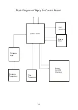
Summary of Contents for Nippy 3+
Page 18: ...16 Fig 3 Inside the base with the control board removed...
Page 32: ...30...
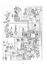
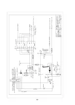
Page 33: ...31 Circuit Diagrams...
Page 34: ...32...
Page 35: ...33 0901 0901 PCB assembly for Control Board primary side 16 11 07...
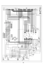
Page 36: ...34 0901 0901 PCB assembly for Control Board secondary side 16 11 07...
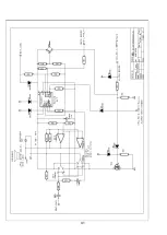
Page 37: ...35 0756 C 17 02 04 A4 1 1 Component Layout for Nippy 3 Command Board 0756 C...
Page 38: ...36...
Page 39: ...37...
Page 40: ...38...
Page 41: ...39...
Page 42: ...40...
Page 43: ...41...
Page 44: ...42 4 7 0 0 u F...