


Contents
Introduction
1
Description
2 - 5
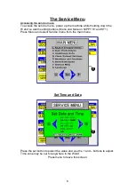
Service Menus
Time and Date
6
Service Period / Calibration
7
Diagnostic Screen
8
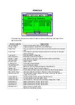
Alarm Log
9
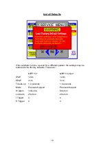
Install Defaults
10
Fault Messages
11-12
Event Log
13
Opening the Case
Fig 1, Opening the Case
14
Fig 2, Inside the base
15
Fig 3, Inside the base
– Control bd removed
16
Fig 4, Location of Components
– Lid
17
Removal of Major Components
18-19
Preventative Maintenance Guide
20
Suggested Acceptance tests
22
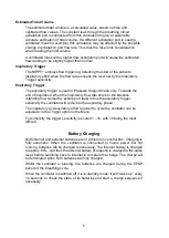
Internal Battery
23
Replacement of Alarm Battery
24
Calibration
25
Theory of Operation
26
System Pneumatic Diagram
27
Block Diagram
28
Block diagram of Control Board
29
Block diagram of Command Board
30
Circuit Diagrams
31- 42
Specification
43
Spare Parts List
44
Summary of Contents for Nippy 3+
Page 18: ...16 Fig 3 Inside the base with the control board removed...
Page 32: ...30...
Page 33: ...31 Circuit Diagrams...
Page 34: ...32...
Page 35: ...33 0901 0901 PCB assembly for Control Board primary side 16 11 07...
Page 36: ...34 0901 0901 PCB assembly for Control Board secondary side 16 11 07...
Page 37: ...35 0756 C 17 02 04 A4 1 1 Component Layout for Nippy 3 Command Board 0756 C...
Page 38: ...36...
Page 39: ...37...
Page 40: ...38...
Page 41: ...39...
Page 42: ...40...
Page 43: ...41...
Page 44: ...42 4 7 0 0 u F...