


14
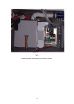
Opening the Case
IMPORTANT Disconnect the ventilator from the mains supply and / or
any external battery.
Invert the ventilator and remove the seven recessed, hexagon socket screws.
Stand the ventilator on its base and ease the lid upwards, away from the rear
panel. When the rear of the lid is clear of the rear panel, lift it from the left
hand side. Disconnect the RS232 connector (4) and the board to board ribbon
cable (3).
1
2
3
4
Fig 1.
Opening the NIPPY
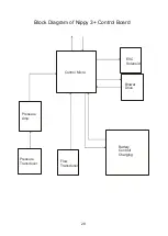
1. Command board
2. Control Board
3. Board to Board Ribbon Cable
4. RS 232 Connection.
Summary of Contents for Nippy 3+
Page 18: ...16 Fig 3 Inside the base with the control board removed...
Page 32: ...30...
Page 33: ...31 Circuit Diagrams...
Page 34: ...32...
Page 35: ...33 0901 0901 PCB assembly for Control Board primary side 16 11 07...
Page 36: ...34 0901 0901 PCB assembly for Control Board secondary side 16 11 07...
Page 37: ...35 0756 C 17 02 04 A4 1 1 Component Layout for Nippy 3 Command Board 0756 C...
Page 38: ...36...
Page 39: ...37...
Page 40: ...38...
Page 41: ...39...
Page 42: ...40...
Page 43: ...41...
Page 44: ...42 4 7 0 0 u F...