


25
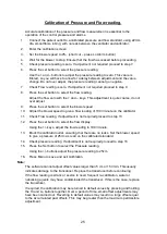
Calibration of Pressure and Flow reading.
Accurate calibration of the pressure and flow measurement is essential to the
operation of the control pressure and alarms.
1.
Connect the patient outlet to a calibrated pressure and flow standard, using 22mm
dia. smoothbore tubing, with no leak between the ventilator and calibrator.
2.
Enter the calibration screen
3.
Set the blower speed to 0%. (short cut
– press Lo Alarm button)
4.
Wait for the blower to stop. Ensure that the flow has ceased before proceeding.
5.
Check pressure reading is zero. If adjustment not required proceed to step 7.
6.
Press the set button to select the pressure reading.
Use the + and
– buttons to adjust the pressure reading to zero. This value is
filtered, so you will have to allow for a delay between adjustment and the value
change. Do not over adjust, the pressure reading cannot go negative.
7.
Check Flow reading is zero. If adjustment not required proceed to step 9.
8.
Press the set button to select the flow reading.
Adjust the flow zero with the + and
– keys. This adjustment is quite coarse, do not
over adjust.
9.
Press the set button to select the blower speed.
10. Adjust the blower speed to give a flow reading of 100 l/minute on the calibrator.
11. Check Flow reading. If adjustment is not required proceed to step 13
12. Press the set button to select the flow display.
Using the +/- keys, adjust the flow reading to 100 l/minute.
13. Block the calibrator outlet, ensuring that there are no leaks. Set the blower speed
to give a pressure of 25cm as read on the calibrated standard.
14. Check pressure reading. If adjustment is not required proceed to step 16
15. Press the Set button to select the Pressure reading.
Using the +/- buttons adjust the pressure reading to 25cm.
16. Press Menu to save and exit calibration.
Note:
The software cannot adjust offset values larger than 5 cm or 15 l/min. This usually
indicates damage to the transducer. Replace the transducer before continuing.
If the flow reading is erratic or seems to need frequent re-calibration, water or
nebulising agents may have contaminated the transducer. If this is the case, replace
the transducer.
If required, the calibration may be returned to default values by pressing and holding
the Hi and Lo buttons together. Over a period of time, small offset adjustments may
have been carried out. Reverting to default values may result in a large offset equal
to the accumulated past offsets. This may be greater than the maximum permissible
adjustment.
Summary of Contents for Nippy 3+
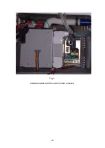
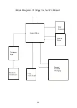
Page 18: ...16 Fig 3 Inside the base with the control board removed...
Page 32: ...30...
Page 33: ...31 Circuit Diagrams...
Page 34: ...32...
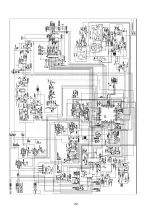
Page 35: ...33 0901 0901 PCB assembly for Control Board primary side 16 11 07...
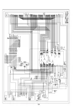
Page 36: ...34 0901 0901 PCB assembly for Control Board secondary side 16 11 07...
Page 37: ...35 0756 C 17 02 04 A4 1 1 Component Layout for Nippy 3 Command Board 0756 C...
Page 38: ...36...
Page 39: ...37...
Page 40: ...38...
Page 41: ...39...
Page 42: ...40...
Page 43: ...41...
Page 44: ...42 4 7 0 0 u F...