background image

Page 9

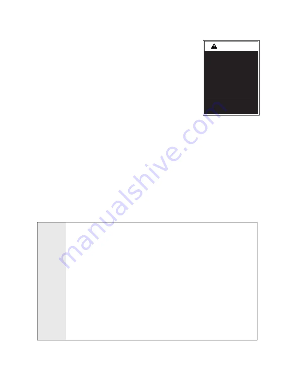
Maintenance and Lubrication Schedule

Maintenance and 

lubrication procedures 

must be performed as 

specified by an 

authorized service 

technician.  Failure to 

do so may result in 

serious bodily injury 

and/or property 

damage.

WA

RNING

Proper maintenance is necessary to ensure safe, 

trouble free operation.  Inspecting the lift for any 

wear, damage or other abnormal conditions should 

be a part of the transit agency daily service program.  

Simple inspections can detect potential problems.  

The maintenance and lubrication procedures speci-

fied in the following schedule must be performed by 

a BraunAbility authorized service representative at 

the scheduled intervals according to the number of 

cycles.  

All service procedures must be performed 

when the lift is fully on the ground.  

NL503 Series 

lifts are equipped with a cycle counter (digital display 

built into the electronic control board). 

NL503 Series lifts are equipped with hardened pins 

and self-lubricating bushings to decrease wear, 

provide smooth operation and extend the service life 

of the lift.      

When servicing the lift at the recommended intervals, 

inspection and lubrication procedures specified in the 

previous sections should be repeated.  Clean com-

ponents and the surrounding area before applying 

lubricants.  Clean only with water, and when cleaned, 

lubricate as directed in the lubrication diagram.  Do 

not use solvents to clean.  

LPS2 General Purpose Penetrating Oil is recom-

mended where Light Oil is called out.  Use of improp-

er lubricants can attract dirt or other contaminants 

which could result in wear or damage to the compo-

nents.  Platform components exposed to contami-

nants when lowered to 

the ground may require 

extra attention.  

Lift components requiring 

grease are lubricated dur-

ing assembly procedures.  

When replacing these 

components, be sure 

to apply grease during 

installation procedures.  

Specified lubricants are 

available from BraunAbili-

ty (part numbers provided 

on previous page).

All listed inspection, lubrication and maintenance proce-

dures should be repeated at 750 cycle intervals follow-

ing the scheduled 4500 cycle maintenance procedures.  

These intervals are a general guideline for scheduling 

maintenance procedures and will vary according to lift 

use and conditions.  Lifts exposed to severe conditions 

(weather, environment, contamination, heavy usage, 

etc.) may require inspection and maintenance proce-

dures to be performed more often than specified.


Discontinue lift use immediately if maintenance and 

lubrication procedures are not properly performed, or if 

there is any sign of wear, damage or improper operation.  

Contact your sales representative or call BraunAbility at 

1-800-946-7513.  One of our Aftersales representatives 

will direct you to an authorized service technician who 

will inspect your lift.

Apply Light Oil - See Lubrication Diagram

Apply Light Oil - See Lubrication Diagram

Apply Light Oil to both sides of slot.  

See Lubrication diagram

Apply Synthetic Grease to both sides of slot.  

See Lubrication diagram

Correct or replace damaged parts. 


Correct or replace damaged parts and/or relubri-

cate.  See Lubrication Diagram

See Certification Checklist Diagnostic Procedures

Correct as needed.

Correct as needed.

Extend outer platform and use compressed air to 

remove any debris in the platform slide plate tracks.  

750 

Cycles

Outer barrier pivot bearings (2)

Outer barrier latch pivot (2)

Outer barrier latch split foot pivot

Outer barrier bracket slot (both sides) - (2)


Inspect outer barrier for proper operation 


Inspect outer barrier latch for proper operation, 

positive securement, and detached or missing 

spring

Verify FMVSS 403 / 404 Certification Checklist

Inspect lift for wear, damage or any abnormal 

condition

Inspect lift for rattles

Platform slide tracks (6)

Summary of Contents for 14122700001

Page 1: ...icles other than motor homes with a gross vehicle weight rating GVWR that exceeds 4 536 kg 10 000 lb DOT Public Use Lift NL503 400649 Rev A January 2016 WARNING Read manual before installing or servic...

Page 2: ...rial No Model No Two BraunAbility Serial No identification tags shown below are posted on the lift One I D tag is posted on the front inner vertical channel A second I D tag is located by the hydrauli...

Page 3: ...Schematic 19 Repair Parts Lift Exploded Views and Parts Lists Mounting Base 20 Upper Lower Control Arms Front 21 Upper Lower Control Arms Rear 22 Inner Vertical Channel Front 23 Inner Vertical Channe...

Page 4: ...Platform Outer Platform Raise Lower Hydraulic Cylinder not visible Outer Barrier Latch Outboard Platform Side Plate Mounting Base Outer Vertical Channel Intermediate Vertical Channel S Beam Transitio...

Page 5: ...roswitch 30205 Full Out Microswitch 30205 Full Out Cam 400024 Full In Cam 400024 Full In Microswitch 30205 Inner Roll Stop Deployed Floor Level Cam Outer 501 2015BM Inner Roll Stop Deployed Floor Leve...

Page 6: ...tivate if the threshold area is occupied when the platform is at least 1 below floor level 1 Make sure connector s to threshold sensors are properly connected 2 Call BraunAbility Aftersales Platform m...

Page 7: ...n the Inner Roll Stop is occupied in the range of 1 below floor level to the point when the Inner Roll Stop is locked in the upright position This deactivation stops the downward travel and triggers a...

Page 8: ...220 CFK 6C9 C18 J13 100 VHA 6C5 C13 HAND 1 INT WAKE 3 1 4 2 103 R55 Y2 8 00M Y1 R54 R57 R60 K11 J23 R61 R52 1002 R42 Lift_Out Floor_SW R41 R40 R39 R27 R77 R53 R68 C10 C5 C8 V104 C4 V104 C17 V104 C14...

Page 9: ...Page 7 NOTES This page intentionally left blank...

Page 10: ...ubrication Diagram Inner Outer Vertical Channel Roller Pins 56 SG Upper Control Arms Pivot Points 12 LO Lower Control Arms Pivot Points 12 LO Intermediate Beam Chain Roller 2 LO Inner Roll Stop Hinge...

Page 11: ...res When replacing these components be sure to apply grease during installation procedures Specified lubricants are available from BraunAbili ty part numbers provided on previous page All listed inspe...

Page 12: ...age and posi tive securement Remove pump module cover and inspect Hydraulic hoses fittings and connections for wear or leaks on pump valve block and hand pump Harness cables wires terminals fuses and...

Page 13: ...rms 2 Outer barrier latch gas springs 2 hairpin Spring tensioner pulley bracket 1 Leaf chain mounting pins 8 Hydraulic Fluid Pump Check level Note Fluid should be changed if there is visible contamina...

Page 14: ...Page 12 NOTES This page intentionally left blank...

Page 15: ...USED OR 20 YL RD 20 RD 20 RD 26 RD 20 RD 20 OR BK 20 WH VT 20 2 1 2 1 YL BK 18 YL WH 18 DK BU 18 2 1 3 2 3 1 2 3 1 5 6 4 5 6 4 1 OR 22 DK BU 18 YL WH 18 YL BK 18 2 1 RD 16 RD 16 BK 16 2 1 2 1 OR 16 RD...

Page 16: ...D WIRE CODE 7 WHITE 22 RED 22 VIOLET 22 BLACK 22 GREEN 22 BLUE 22 ORANGE 20 ORANGE 22 6 5 4 3 2 1 COLOR NO 7 COND WIRE CODE 7 YELLOW BLACK 18 YELLOW WHITE 18 ORANGE 22 DARK BLUE 18 4 3 2 1 COLOR NO 4...

Page 17: ...Page 15 NOTES This page intentionally left blank...

Page 18: ...ttings 402043KS 18 1 Cylinder In Out Front 1514 3 9900A 19 1 Cylinder In Out Rear 1514 3 9800A 20 3 Fitting Tee 7 16 20 JIC 37 Male x 3 30793 21 1 Valve Pressure Compensator 30281 22 1 Handle w Grip 1...

Page 19: ...16 17 17 10 25 15 15 19 18 7 1 2 12 10 30 7 10 10 10 20 28 20 29 9 10 20 24 5 6 5 14 4 26 21 35 23 10 10 10 10 9 13 11 11 15 9 9 36 Arrow must face valve block Discard bolt and nut when replacing hand...

Page 20: ...D 10 ITEMS NOT SHOWN 1 38144A HARN NL501 INTERLOCK NUT 1 4 20 HEX LOCK AUTO BK BOLT 1 4 20 X 3 1 2 HEX SPACER VALVE BLOCK NL501 ELBOW 7 16 20 M O RING 37 KNOB KNURLED MANUAL VALVE NL500 BLOCK MANUAL V...

Page 21: ...V1 RV2 Front In Out Cylinder Rear In Out Cylinder D Valve C Valve B Valve 1500 PSI Fixed Displacement Pump Vented Reservoir Backup Pump Single Acting Cylinder Check Valve 2 Way 2 Position Solenoid Val...

Page 22: ...5 16 18 X 1 HEX HD CAP 24505 2 ELBOW 45 7 16 20 7 16 20 SAE MALE O RING 100524 002 1 ASSEMBLY E J LIFT CONTROLLER 51267 1 GROM ID 88 GR 06 GD 1 25 T 30 87592 2 FITTING 90 DEG 4JICFX 4JICM 82064 4 BUMP...

Page 23: ...ARM TIE BAR 15 1 501 0045FA ASSY LOWER OUTER FR CONTROL ARM 16 1 501 0055FA ASSY FRONT CONTROL ARM 17 1 34832 COLLAR DBL SPLIT 3 4 ID BLK OXIDE 18 1 936 0403 PIN PIVOT PARALLEL ARM 19 1 25346 WASHER...

Page 24: ...19 1 501 0056RA ASSY RR LINK OUTER 20 1 501 0045RA ASSY LOWER OUTER RR CONTROL ARM 21 1 501 0048A ASSY H BRACE 22 1 501 0044RA ASSY UPPER OUTER RR CONTROL ARM 23 1 936 0403 PIN PIVOT PARALLEL ARM 24...

Page 25: ...2 1 PIN COTTERED 4x4 LEAF CHAIN PART NO QTY ITEM DESCRIPTION PART NO QTY ITEM DESCRIPTION CHAIN LEAF 4x4 5 PITCH x 41 CYLINDER ORIFICE FITTING KIT 2 FITTINGS CLIP CABLE 3 8 PLASTIC PIN COTTER 1 32 x 1...

Page 26: ...NL500 BUMPER RUBBER 1 5 16 18 x 5 8 STUD PIN COTTERED 466 CHAIN LO PRO HEAD CHAIN LEAF 4x4 5 PITCH x 41 CHAIN LEAF 4x4 5 PITCH x 21 30375 16 2 SCREW 10 32 x 1 2 BHSCS AUTO BLACK 21759 2 PIN COTTERED 4...

Page 27: ...BLUE 242 BA 18822 OR EQUIVALENT ON THREADS 1 500 0111A 81039 000 500 2112 501 2100WBKN 2 1 1 1 SCREW 1 4 20 X 5 8 BHSCS ZINC PIN ROLLER I BEAM I BEAM WELDMENT ASSY ROLLER CHAIN I BEAM 23173 21708R021...

Page 28: ...8 x 3 8 BHCS SS CAM INNER MICRO SWITCH FLR LVL INR ROL STOP DEPLOY CAM OUTER MICRO SWITCH FLR LVL INR ROL STOP DEPLOY 21708R021 21759 23173 10 9 8 1 1 1 CHAIN LEAF 4x4 5 PITCH x 21 500 2736BM 11 1 GUA...

Page 29: ...ARING FLANGE 1 2 x 1 4 08FDU04 24537 2 SCREW 10 32 x 3 8 FL HD HX SKT AUTO BK 35 34346 1 BUMPER UHMW 1 x 0 234 36 23173 1 PIN COTTER 1 32 x 1 2 4x4 37 34575 1 PIN COTTERED 466 CHAIN LO PRO HEAD 38 343...

Page 30: ...FORM PIVOT 34347BBM 20 1 HANDRAIL MOUNTING SHAFT BOTT RR NL500 BOLT 3 8 16 X 3 4 FLBHSCS GD8 RING 1 2 EXT SELF LOCK SNAP AUTO BK BALL STUD 10mm SEAT LIFT A 9008 2 500 0109YL 24442 990 0341 500 0047BM...

Page 31: ...5 1 1 1 1 SHAFT HANDRAIL PIVOT NL500 HR CAM FOLLOWER 1 28983 MOD BUCKEL HALF ASSY VISTA NON INTERLOCKED 7 1 25171 BOLT 5 16 18 X 2 FLBHSCS GD8 8 1 10059BKWP NUT 3 8 16 HEX AUTO BK WITH PATCH 9 1 3481...

Page 32: ...ATTACHMENT BRACKET ON THE BOTTOM SIDE OF THE PLATFORM INNER DECK 3 USE 3 SCREWS FROM INNER ASSEMBLY TO INSTALL GUARD INTO PLACE 4 APPLY LOCTITE THREADLOCKER BLUE 242 BA 18822 OR EQUIVALENT ON THREADS...

Page 33: ...V POP SD64BS 3 16 13 25 AUTO BK 35031 1 GAS SPRING 14 47 EXT 9 02 COM P1 1150N 11513 1 RIV POP SD64BS 3 16 13 25 AUTO BK 1 3 500 0209BM BRACKET GAS SPRING MOUNT PLATFORM 11387BK 3 5 16 18 NUT AUTO BLA...

Page 34: ...SLIDETRACK OUTER FRONT BOTTOM DESCRIPTION PART NO ITEM QTY 4 3 2 1 6 5 7 8 9 10 DESCRIPTION PART NO ITEM QTY 3 5 2 8 1 9 10 7 4 6 SIDERAIL INNER PLATFORM NL500 34410BM SCREW 1 4 20 X 875 BHSC 500 030...

Page 35: ...0 X 1 3 4 SHCS GRADE 8 34 10058 2 NUT 5 16 18 HEX AUTO BK 32 33411BM 2 BRACKET ADJUST SPLIT FOOT 40 34779 1 STRAIN RELIEF OUTER BARRIER HARNESS 38 34686 2 PIN ROLLSTOP GAS SPRING 37 945 2206RNBM 1 LAT...

Page 36: ...QTY ITEM PART NUMBER DESCRIPTION 3 2 1 1 1 1 29857 31787 400623BM DIODE GREEN LED PANEL MOUNT 24V SWITCH TOGGLE W GOLD CONTACTS SPADE TERM BKT MTG GREEN LED POWER SWITCH NL503 QTY ITEM PART NUMBER DES...

Page 37: ...anyone Braun reserves the right to make changes in the design or material of its products without incurring any obligation to incorporate such changes in any previously manufactured product Braun mak...

Page 38: ...by another entity Note the written warranty provided by the manufacturer of the material component or part is the direct responsibility of that manufacturer items that are added or changed after the...

Page 39: ...tates do not allow a reduction in the statute of limitations so this reduction may not apply to you WARRANTY REGISTRATION and MISCELLANEOUS Your warranty registration records should be completed and d...

Page 40: ...vailable at the time of publication BraunAbility reserves the right to make changes at any time without notice 400649 Rev A January 2016 631 West 11th Street P O Box 310 Winamac IN 46996 USA Phone 1 5...

Reviews: